
Grounding lug

a grounding conductor and conductor technology, applied in the direction of electric connection bases, connection contact member materials, coupling device connections, etc., can solve the problem of less than ideal for running grounding conductors underneath strings of photovoltaic modules, and achieve the effect of facilitating the installation of wires

Active Publication Date: 2012-04-10
ERICO INT
View PDF3 Cites 11 Cited by
  • Summary
  • Abstract
  • Description
  • Claims
  • Application Information

AI Technical Summary

Benefits of technology

Facilitates easier and more secure installation of grounding wires, reducing installation time and overall cost-per-watt for solar PV modules while maintaining grounding continuity.

Problems solved by technology

Direct-bury lugs were designed for other purposes, such as bonding metallic conduits, which make them less than ideal for running grounding conductors underneath strings of photovoltaic modules.

Method used


Image

  • Grounding lug
  • Grounding lug
  • Grounding lug

Examples


Embodiment Construction

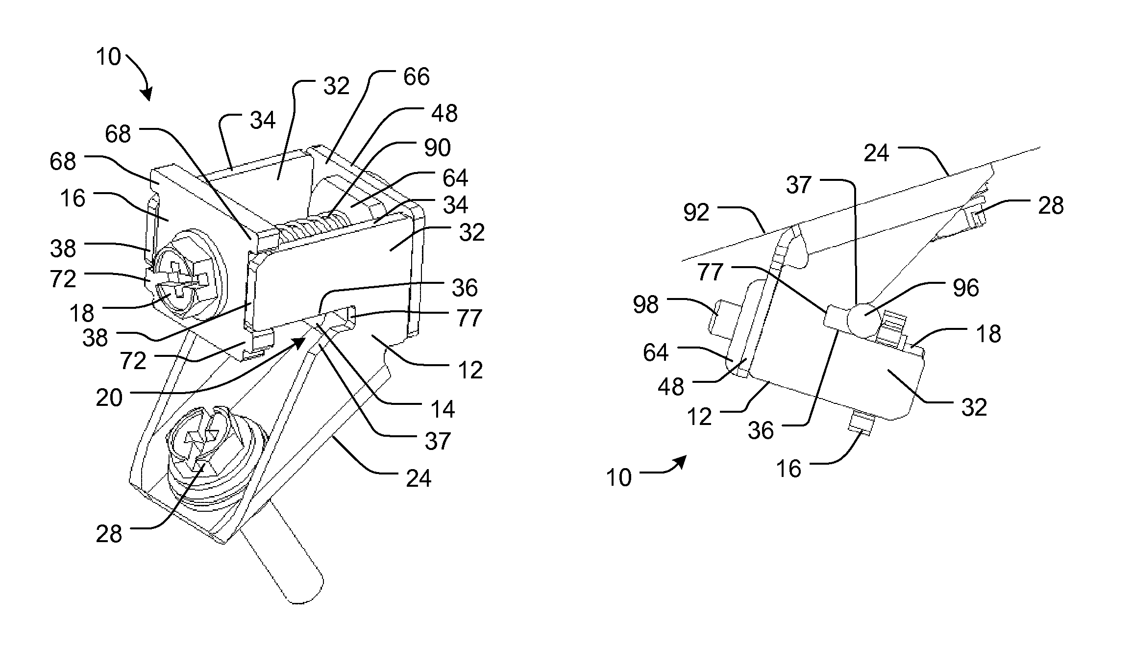
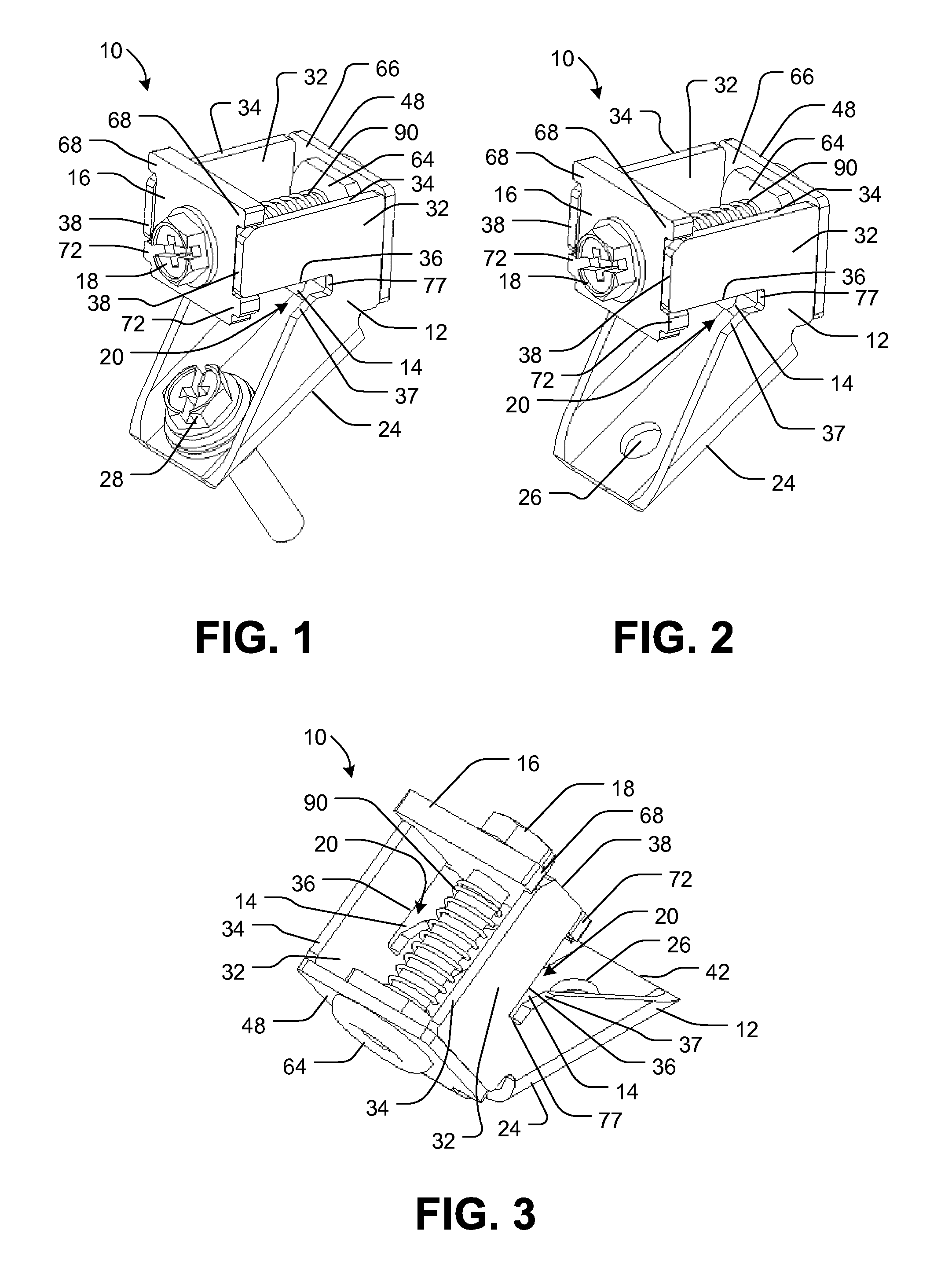
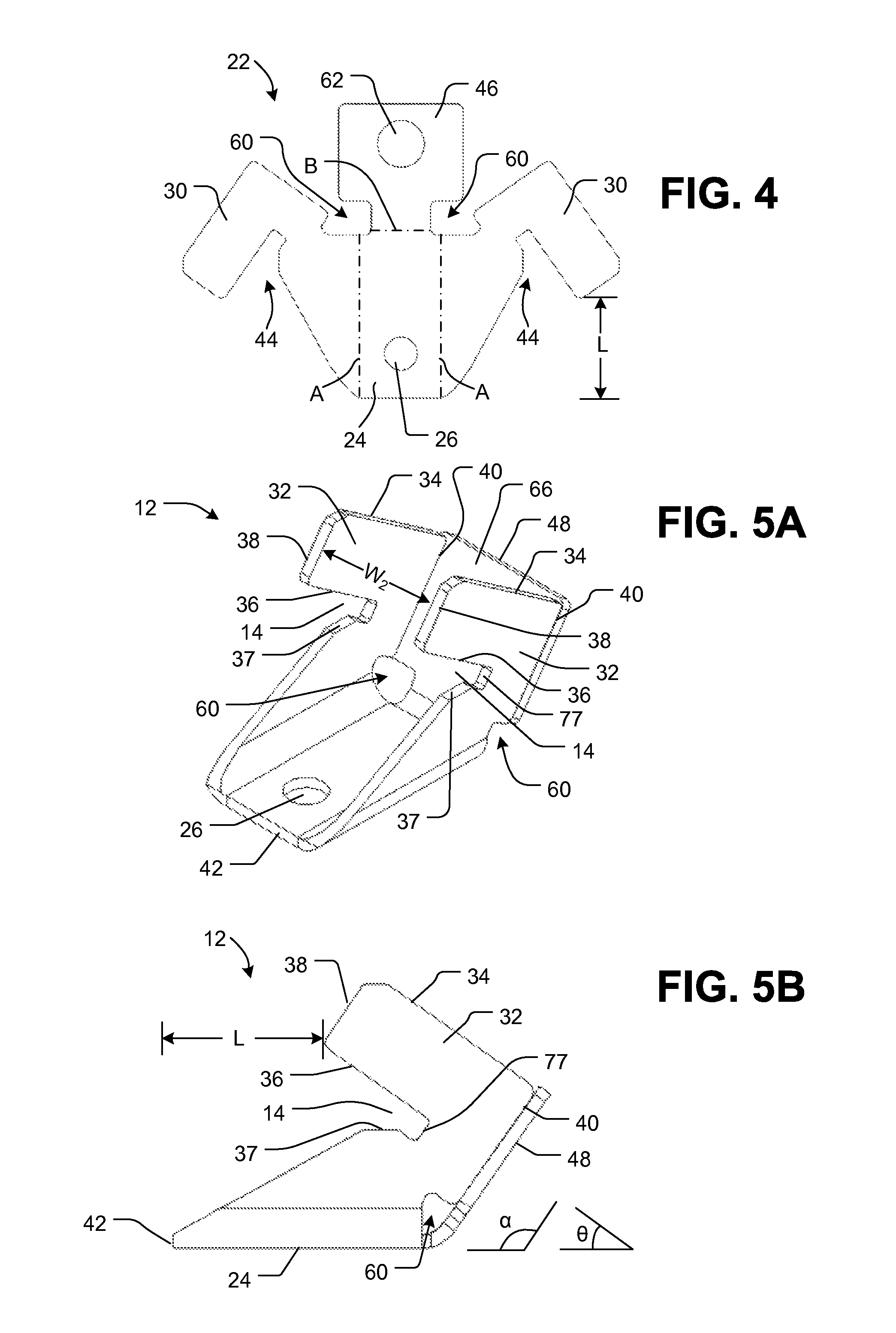
[0029]Referring now to the drawings in detail and initially to FIGS. 1-3, an exemplary grounding lug according to the invention is indicated generally at 10. The grounding lug 10 includes a housing 12 having an opening 14 (also referred to as a “lay-in slot” or a “slot”) for receiving a wire (also referred to as a “grounding wire”), a clamping pad 16 (also referred to as a “grounding clamp”) movable relative to the housing, and a moving mechanism 18 coupled to the housing 12 and the clamping pad 16. The moving mechanism 18 moves the clamping pad 16 between an unclamped position (shown in FIGS. 1-3) in which the clamping pad 16 defines a wire-receiving pocket 20 in combination with the opening 14, and a clamped position (shown in FIG. 14) in which the clamping pad 16 clamps the wire to the housing 12.

[0030]With additional reference to FIGS. 4, 5A and 5B, the housing 12 of the exemplary grounding lug 10 is shown in more detail. FIG. 4 shows an exemplary blank 22 for forming the housin...


PUM

PropertyMeasurementUnit
acute angleaaaaaaaaaa
lengthaaaaaaaaaa

Abstract

A grounding lug for holding a grounding wire includes a housing defining an opening for receiving a wire and a clamping pad movable relative to the housing. The clamping pad is movable between an unclamped position in which the clamping pad defines a wire-receiving pocket in combination with the opening defined by the housing, and a clamped position in which the clamping pad clamps the wire to the housing. The grounding lug also includes a moving mechanism coupled to the housing and the clamping pad for moving the clamping pad between the unclamped and clamped positions.

Description

RELATED APPLICATIONS[0001]This application claims the benefit of U.S. Provisional Application No. 61 / 225,316, filed Jul. 14, 2009, which is hereby incorporated herein by reference.FIELD OF THE INVENTION[0002]The present invention generally relates to hardware for an electrical fixture and more specifically, to a grounding conductor for a grounding wire.DESCRIPTION OF THE RELATED ART[0003]According to 2008 National Electrical Code Article 690.43, solar photovoltaic module frames and supporting structures must be grounded when installed. There currently are a few different options available to help meet this requirement. The most common option is a “direct-bury” lay-in lug, which is either extruded or cast, commonly from tinned copper. Direct-bury lugs were designed for other purposes, such as bonding metallic conduits, which make them less than ideal for running grounding conductors underneath strings of photovoltaic modules.SUMMARY OF THE INVENTION[0004]The present invention provide...

Claims


Application Information

Patent Timeline
Patent Type & Authority Patents(United States)
IPC IPC(8): H01R4/38
CPCH01R4/38H01R4/64Y10T29/49204
Inventor BOLING, DALE R.AMBROGIO, NICHOLAS J.FLEMMING, MATTHEW
Owner ERICO INT
Learn More