Methods and apparatus for flow control associated with multi-staged queues

a flow control and multi-stage technology, applied in the field of flow control, can solve the problems of loss of at least portions of data, disruption of data transmission from a transmitter to a receiver via a physical link (e.g., an ethernet link),

Active Publication Date: 2012-04-10
JUMIPER NETWORKS INC
View PDF92 Cites 21 Cited by
  • Summary
  • Abstract
  • Description
  • Claims
  • Application Information

AI Technical Summary

Problems solved by technology

Transmission of data from a transmitter to a receiver via a physical link (e.g., an Ethernet link) can be, for example, disrupted because of congestion at a queue configured to receive the data.
In some instances, the disruption can cause head-of-line (HOL) blocking and / or result in the loss of at least portions of the data due to buffer overflow.
These known flow control protocols, however, may not adequately resolve congestion issues related to multi-stage queues and / or may not adequately handle the onset of congestion within a hop-by-hop network link caused by, for example, bursts of data.

Method used


Image

  • Methods and apparatus for flow control associated with multi-staged queues
  • Methods and apparatus for flow control associated with multi-staged queues
  • Methods and apparatus for flow control associated with multi-staged queues

Examples


Embodiment Construction

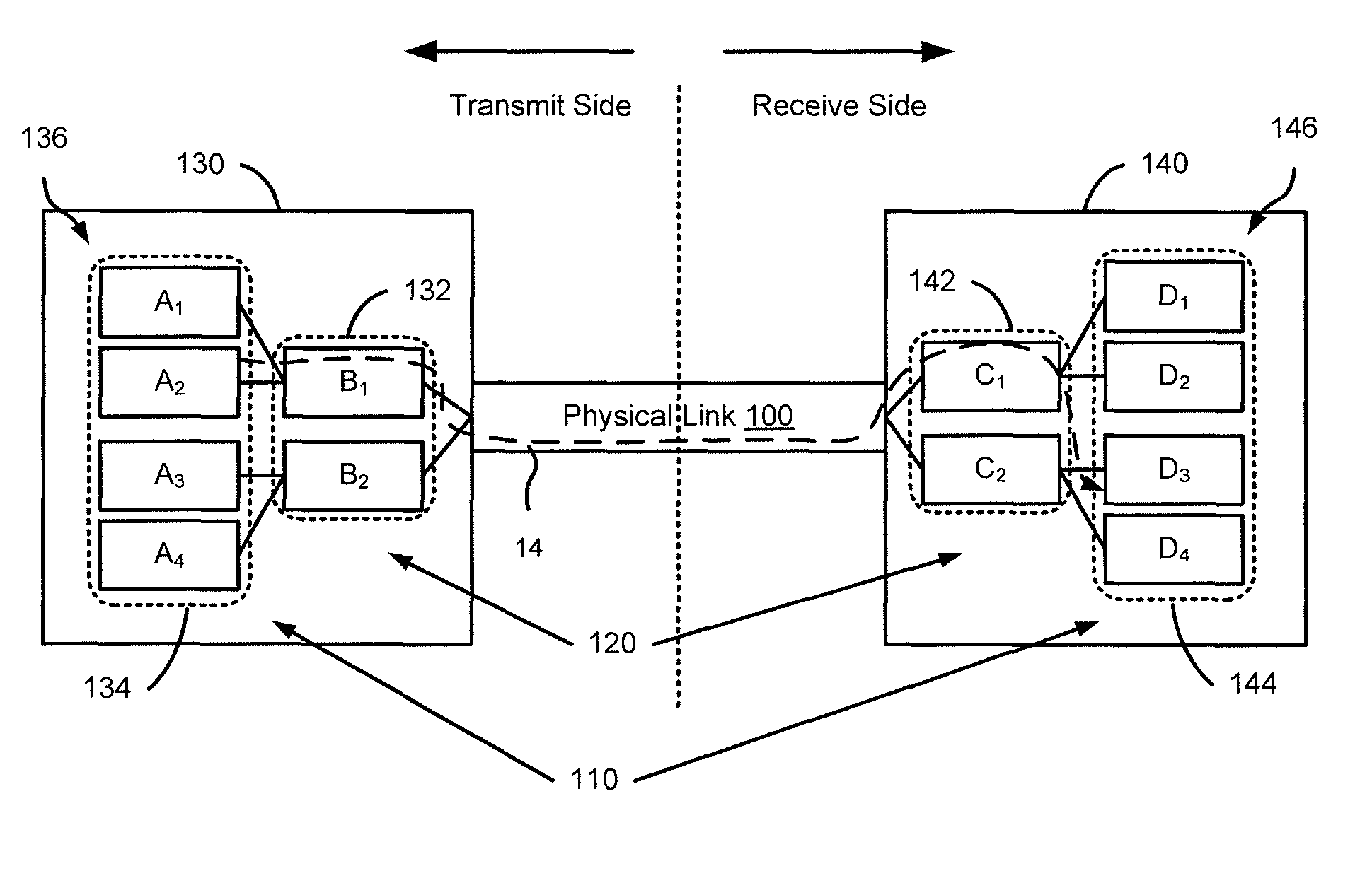
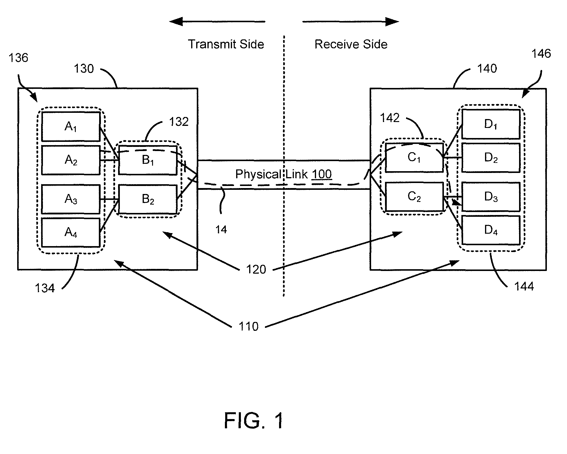
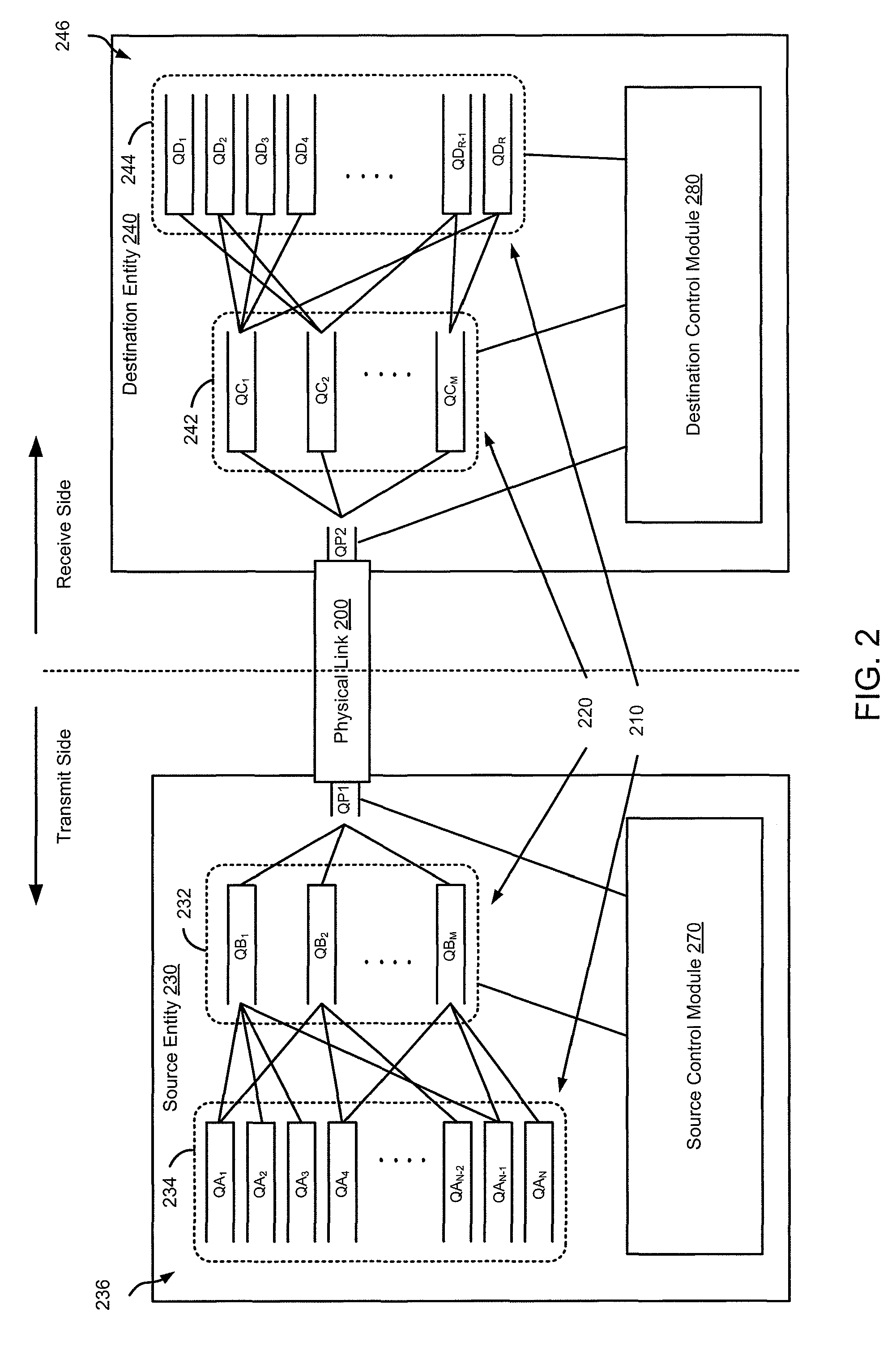
[0013]Flow of data (e.g., a data packet such as an internet protocol (IP) packet) via a link between stages of queues at a source entity and stages of queues a destination entity can be controlled based on flow control signaling associated with multiple flow control loops. For example, if the destination entity (or a portion thereof) is unable to handle a flow of data from the source entity because the destination entity has limited buffering capability relative to the amount of data being sent, the destination entity can send a flow control signal associated with at least one of the flow control loops to the source entity. The flow control signal can be configured to trigger the source entity to suspend transmission of the flow of data to the destination entity. In some embodiments, the link between the source entity and the destination entity can be a physical link and can be associated with a single network hop (e.g., a network step that cannot be defined topographically, or a ne...


PUM


Abstract

In one embodiment, a method, comprising receiving at a receive side of a physical link a request to suspend transmission of data from a queue within a transmit side of a first stage of queues and to suspend transmission via a path including the physical link, a portion of the first stage of queues, and a portion of a second stage of queues. The method includes sending, in response to the request, a flow control signal to a flow control module configured to schedule transmission of the data from the queue within the transmit side of the first stage of queues. The flow control signal is associated with a first control loop including the path and differing from a second control loop that excludes the first stage of queues.

Description

RELATED APPLICATION[0001]This application claims priority to the commonly owned U.S. Provisional Patent Application No. 61 / 096,209, entitled “Methods and Apparatus Related to Flow Control within a Data Center,” filed on Sep. 11, 2008, which is incorporated herein by reference in its entirety. This application is related to a co-pending U.S. patent application 12 / 242,230, filed on even date herewith, entitled “Methods and Apparatus for Flow-Controllable Multi-Staged Queues,” which is incorporated herein by reference in its entirety.BACKGROUND[0002]Embodiments described herein relate generally to flow control, and, in particular, to flow control associated with multi-staged queues.[0003]Transmission of data from a transmitter to a receiver via a physical link (e.g., an Ethernet link) can be, for example, disrupted because of congestion at a queue configured to receive the data. In some instances, the disruption can cause head-of-line (HOL) blocking and / or result in the loss of at leas...

Claims


Application Information

Patent Timeline
Patent Type & Authority Patents(United States)
IPC IPC(8): H04L12/24H04L47/30H04L47/6275
CPCH04L12/5693H04L47/11H04L47/26H04L47/60H04L49/90H04L47/263H04L47/30H04L47/10H04L47/266H04L49/505H04L47/50
Inventor GODBOLE, AVANINDRASINDHU, PRADEEPFRAILONG, JEAN-MARC
Owner JUMIPER NETWORKS INC
Why Eureka
Try Eureka