
Method and apparatus for transmitting and receiving different signal types in communication systems

a communication system and signal type technology, applied in the field of wireless communication systems, can solve the problems of increasing the complexity of the node b receiver, compromising the accuracy of the cqi reception and the rr or sr reception, and the overhead of the system, so as to achieve the effect of consuming additional bandwidth resources

Active Publication Date: 2012-04-10
UNWIRED PLANET INT LTD
View PDF11 Cites 14 Cited by
  • Summary
  • Abstract
  • Description
  • Claims
  • Application Information

AI Technical Summary

Benefits of technology

"The present invention provides an apparatus and method for multiplexing the transmission of a reference signal from a UE that does not have any other signal transmission with the transmission of a reference signal from another UE that also transmits a data signal or a control signal during the same transmission time interval. This allows for sounding of the operating bandwidth without consuming additional bandwidth resources in the communication system. Additionally, the invention allows a UE to transmit state information, such as a release request or a service request, without consuming additional bandwidth resources in the UL of the communication system."

Problems solved by technology

The first prior art option introduces additional UL overhead and system complexity as a new channel needs to be defined and supported.
The second prior art option typically compromises the accuracy of the CQI reception and of the RR or SR reception, and increases the complexity of the Node B receiver.

Method used


Image

  • Method and apparatus for transmitting and receiving different signal types in communication systems
  • Method and apparatus for transmitting and receiving different signal types in communication systems
  • Method and apparatus for transmitting and receiving different signal types in communication systems

Examples


first embodiment

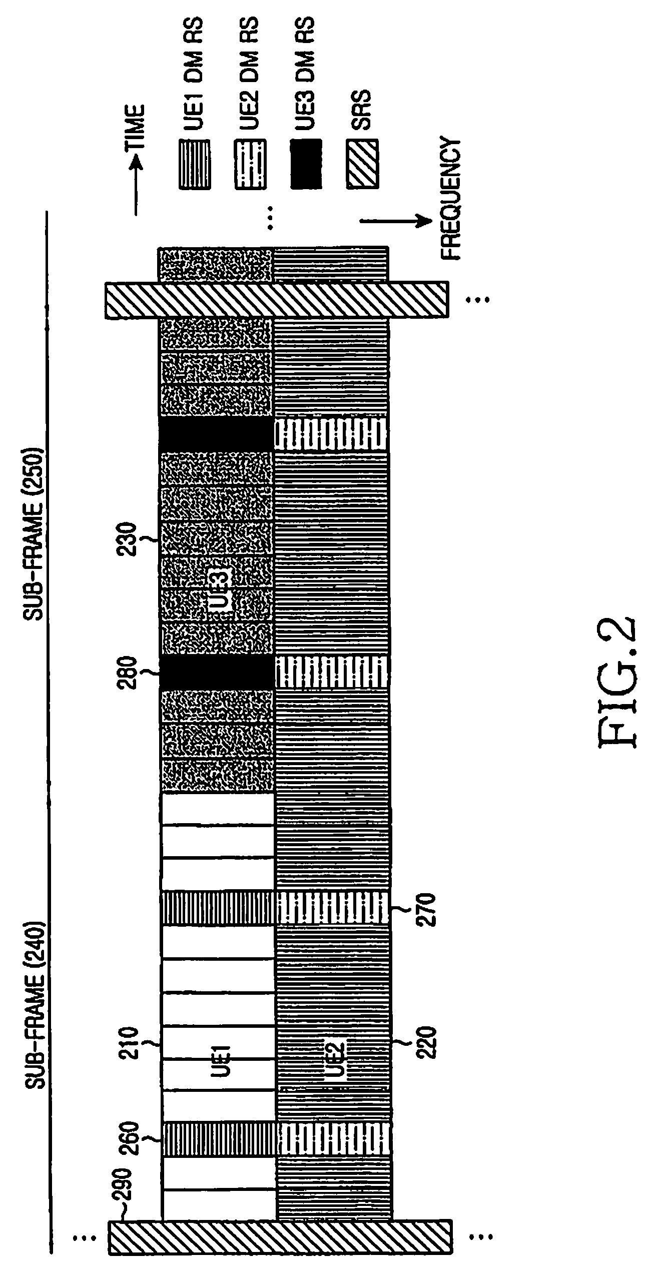
[0078]In a first embodiment, the present invention assumes that a UE is assigned at least two cyclic shift values. The first cyclic shift value can be used either for DM RS transmission in the PUSCH as illustrated in FIG. 1, or for PUCCH transmission as illustrated in FIG. 9 or FIG. 10. The second cyclic shift value is used for RS transmission without any other (non-RS) signal transmission in the respective TTI either during the DM RS symbols in the PUSCH or throughout the PUCCH. This RS serves either as an RR or as an SR and is multiplexed with the DM RS or the PUCCH transmission from another UE, which uses a third cyclic shift value which may be the same as the first cyclic shift value.

[0079]A fourth cyclic shift value may be reserved to never be used, either for the DM RS in the PUSCH or for the PUCCH, so that the serving Node B can determine whether either a RR or a SR was transmitted. This can be achieved by comparing the output energy between the demodulation results using the...

second embodiment

[0080]In a second embodiment, the present invention assumes that a UE is assigned at least three cyclic shift values. The first cyclic shift value is used for the transmission of a DM RS in the PUSCH as illustrated in FIG. 1 or for PUCCH transmission as illustrated in FIG. 9 or FIG. 10. The second and third cyclic shift values are used for transmission of a RS without any other (non-RS) signal transmission in the corresponding TTI to indicate, respectively, an RR and the opposite of an RR (that is, that the UE still has data to transmit). The RS using the second or third cyclic shift value can be multiplexed with the DM RS of another UE having PUSCH transmission and using a fourth cyclic shift value, which may be the same as the first cyclic shift value, or with the PUCCH transmission of another UE using a fourth cyclic shift value. The Node B determines whether an RR or its opposite was sent by correlating the received signal during the RS symbols in the PUSCH or during the entire ...


PUM


Abstract

A method and apparatus for multiplexing a reference signal from a User Equipment (UE), not having any other signal transmission in the respective Transmission Time Interval (TTI), with a reference signal from another UE also having data transmission in the respective TTI, or with the control signal and reference signal from another UE transmitted in the respective TTI. The multiplexed reference signal from the UE not having any other signal transmission in the respective TTI can serve as a sounding reference signal to enable the serving base station to apply link adaptation to a subsequent signal transmitted by the UE or it can serve as a reference signal conveying state information, such as resource request or service request.

Description

PRIORITY[0001]This application claims priority to U.S. Provisional Application No. 60 / 962,584 entitled, “Transmission of Sounding Reference Signals for VoIP Type Services in SC-FDMA Communication Systems”, which was filed on Jul. 30, 2007, and to U.S. Provisional Application No. 60 / 974,305 entitled, “Transmission of Sounding Reference Signals for VoIP Type Services in SC-FDMA Communication Systems”, which was filed on Sep. 21, 2007, the contents of which are incorporated herein by reference.BACKGROUND OF THE INVENTION[0002]1. Field of the Invention[0003]The present invention is directed, in general, to wireless communication systems and, more specifically, to a Single-Carrier Frequency Division Multiple Access (SC-FDMA) communication system.[0004]2. Description of the Art[0005]In particular, the present invention is directed to the transmission and multiplexing of Reference Signals (RSs) in SC-FDMA communication systems.[0006]Several types of signals should be supported for the prop...

Claims


Application Information

Patent Timeline
Patent Type & Authority Patents(United States)
IPC IPC(8): H04B7/208H04J1/00
CPCH04L5/0007H04L5/0037H04L27/261H04L5/0053H04L5/026H04L5/0051H04B7/2656H04J11/0023H04W72/21
Inventor PAPASAKELLARIOU, ARISCHO, JOON-YOUNG
Owner UNWIRED PLANET INT LTD
Learn More