Landing flap drive system

a technology of landing flap and drive system, which is applied in the direction of aircraft power plants, transportation and packaging, with power amplification, etc., can solve the problems of considerable installation cost of the final assembly of such a system, and achieve the effect of improving the landing flap drive system

Active Publication Date: 2012-04-17
DEUTSCHES ZENTRUM FUER LUFT & RAUMFAHRT EV +1
View PDF24 Cites 13 Cited by
  • Summary
  • Abstract
  • Description
  • Claims
  • Application Information

AI Technical Summary

Benefits of technology

[0007]By integrating the entire drive system in the track, the installation and the integration of the landing flap drive system in the aircraft may be facilitated to a significant extent. Furthermore, the production expenditure or pre-installation expenditure may be reduced because all the drive components can be integrated in the track beforehand, in the factory, prior to final assembly of the track.
[0008]According to a further embodiment, the landing flap drive system further comprises a step-down gear arrangement to reduce the operational speed of the landing flap.
[0011]In this way, drive redundancy may be provided which may further enhance system safety and may minimise the risk of failure. Furthermore, for example, when a considerable load is experienced, the second drive motor may be switched on if necessary so as to improve the drive performance.
[0018]In this way, the effort required for installing the landing flap drive system during final assembly may be considerably reduced in that the landing flap drive system that is integrated in the track is attached to the first attachment region on the wing of the aircraft. Essentially there may be no need for any more extensive installation beyond this. On the second attachment region, the landing flap drive system may simply be connected to the landing flap such that the landing flap can be operated.
[0020]According to this embodiment, the interfaces may be installed correspondingly already in the context of preassembly or pre-installation such that during final assembly, simple connection of the supply lines or signal lines to the landing flap drive system is all that is required.
[0025]The landing flap drive system, for example, may be integrated in the track prior to final assembly of the track. Such complete integration in the track may considerably reduce the effort required for assembly. There may be no need to provide structural leadthroughs through the fuselage and the trailing edge of the wing and the associated deflection gear and universal joints of the shaft arrangement that are necessary in centrally driven landing flaps. During final assembly, a track that is equipped with all the system components may only need to be attached underneath the wing and may need to be connected to the supply lines and signal lines and to the flap structure. Furthermore, the design space problems of redundant drives to be installed on the trailing edge of the wing may be solved in this way.

Problems solved by technology

The installation expense of the final assembly of such a system may be considerable.

Method used


Image

  • Landing flap drive system
  • Landing flap drive system
  • Landing flap drive system

Examples


Embodiment Construction

[0040]The examples described and drawings rendered are illustrative and are not to be read as limiting the scope of the invention as it is defined by the appended claims.

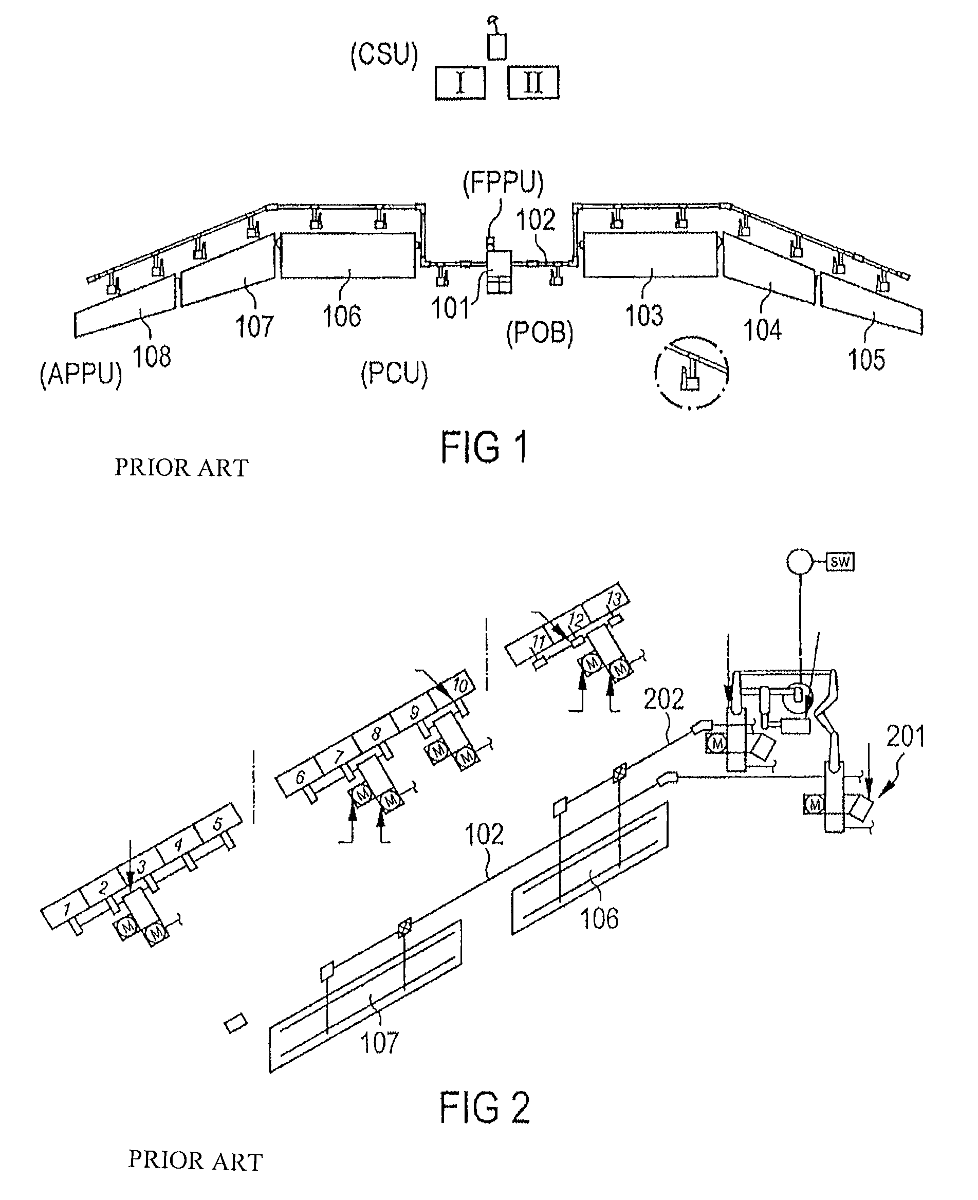
[0041]FIG. 1 shows a diagrammatic view of a landing flap system. Today's landing flap drive systems, generally speaking, comprise a central drive 101 arranged in the fuselage, and a central shaft arrangement 102. The central shaft arrangement 102 is used to transmit the driving power from the motor 101 to the individual landing flaps 103, 104, 105, 106, 107, 108. This may require extensive installation work such as, for example, leadthroughs in the fuselage.

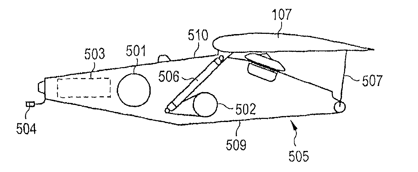
[0042]FIG. 2 shows a diagrammatic view of a further landing flap system. As shown in FIG. 2, in this arrangement two shaft arrangements 102, 202 have been provided for reasons of redundancy, wherein the flaps 106, 107 of the left-hand wing, and the flaps of the right-hand wing (not shown in FIG. 2) are mechanically coupled to each other.

[0043]The landing flap sys...


PUM


Abstract

A landing flap drive system, in one example, includes a first drive motor for operating a landing flap. In this arrangement, the landing flap drive system is integrated in a track of the landing flap such that final assembly and integration of the system are facilitated to a significant extent.

Description

REFERENCE TO RELATED APPLICATIONS[0001]This application claims the benefit of the filing date of German Patent Application No. 10 2005 017 307.1 filed Apr. 14, 2005 and of U.S. Provisional Patent Application No. 60 / 671,386 filed Apr. 14, 2005, the disclosure of which applications is hereby incorporated herein by reference.FIELD OF THE INVENTION[0002]The field relates to landing flap systems for aircraft.BACKGROUND OF THE INVENTION[0003]Today's landing flap drive systems, comprise a central drive with a central shaft transmission to the drive stations. Apart from these, for reasons of redundancy, there are also solutions involving two shaft arrangements, wherein the flaps of the left-hand and the right-hand wing are mechanically coupled together. These are drive systems in which generation of the mechanical drive performance takes place so as to be locally separated from the power takeoff at the individual drive stations that are distributed along the wing.[0004]In landing flap syste...

Claims


Application Information

Patent Timeline
Patent Type & Authority Patents(United States)
IPC IPC(8): B64C9/00B64C9/02B64C13/50
CPCB64C9/16B64C13/24B64C13/50B64D45/0005B64D2045/001
Inventor RECKSIEK, MARTINGIEBELER, CHRISTOPHBRUECKNER, INA
Owner DEUTSCHES ZENTRUM FUER LUFT & RAUMFAHRT EV
Why Eureka
Try Eureka