Method and device enabling an athlete to determine and then control the rate of displacement of a mass

a technology of displacement rate and device, which is applied in the field of method and device enabling an athlete to determine and then control the displacement rate of a mass, can solve the problems of not allowing for example the maximum power of a muscle group of an athlete to be measured, and none of these devices allows basic physiological muscle parameters such as strength, speed or power of a muscle group to be obtained

Active Publication Date: 2012-04-17
SLYDE ANALYTICS LLC
View PDF22 Cites 7 Cited by
  • Summary
  • Abstract
  • Description
  • Claims
  • Application Information

AI Technical Summary

Benefits of technology

[0017]There is thus a need in the state of the art for a method and a device for improving the efficiency and the quality of the training plans of any athlete in the field of sports.
[0019]There is also a need for an accelerometer and for a method enabling an athlete to determine training setpoints, i.e. values for the mass to be displaced, rate of displacement and / or number of displacements or series of displacements, in order to improve the muscle power of a specific muscle or muscle group. Muscle power is understood in the present application to be the ability to displace a given mass at a given speed for a given number of times.
[0020]There is also a need for an accelerometer and for a method allowing the compliance with these setpoints during training to be controlled and enabling these setpoints to be adapted to the progress and measurements during training.
[0022]According to one aspect, the method enables the athlete to determine the optimum mass to be lifted for each type of exercise, depending on the athlete's objectives, as well as the speed or rate at which this mass must be lifted. During training, the inventive device makes it possible to check whether the mass is indeed lifted at the correct rate and to then adapt the mass and rate setpoints for future training sessions according to the measured acceleration values.

Problems solved by technology

It is however not adapted for muscle training and for measuring short efforts, and does not allow for example the maximum power of a muscle group of the athlete to be measured.
None of these devices allows basic physiological muscle parameters such as strength, speed or power of a muscle group to be obtained.
They are essentially suited for endurance sports, for example for jogging, and are not or only poorly adapted for the specific training of the force, power or speed of contraction of a muscle or muscle group.
Without knowing the displaced mass, many devices do not make it possible to deduce the athlete's force or power.
Even if this mass is known, many devices aim first and foremost to calculate the distance travelled, the average speed or the energy output, but do not allow the muscle power of a muscle group of the athlete to be determined directly, i.e. the speed at which this muscle group can displace a given mass.
It is however not suited for measuring the athlete's muscular performance.
Furthermore, the use of electrodes makes it inconvenient to use.
This system is complex, since it makes use of several sensors, including expensive and relatively fragile gonometers.
The connection of the sensors to one another and with the external computer increases the cost of the device and makes it difficult to install.
It is adapted for training precise movements, for example a golf swing, but does not allow the muscle power developed by the athlete during this movement to be determined directly.
The apparatus is not portable and is suited only to combat sports such as boxing, karate, etc.
However, this device supplies no indication to the athlete as to the rate at which this load is to be displaced in order to achieve the desired results.
For example, this device does not distinguish between an athlete wishing to improve speed and another athlete wishing to improve power.
Finally, this device is designed for short tests only, using a series of exercises imposed by the device (for example 5 jumps, 5 lifts, etc.); an error is generated if the athlete executes different movements or a different number of movements from what is prescribed by the test.
This devices is thus not adapted for measuring physiological parameters during training, for example when the number of movements varies.

Method used


Image

  • Method and device enabling an athlete to determine and then control the rate of displacement of a mass
  • Method and device enabling an athlete to determine and then control the rate of displacement of a mass
  • Method and device enabling an athlete to determine and then control the rate of displacement of a mass

Examples


Embodiment Construction

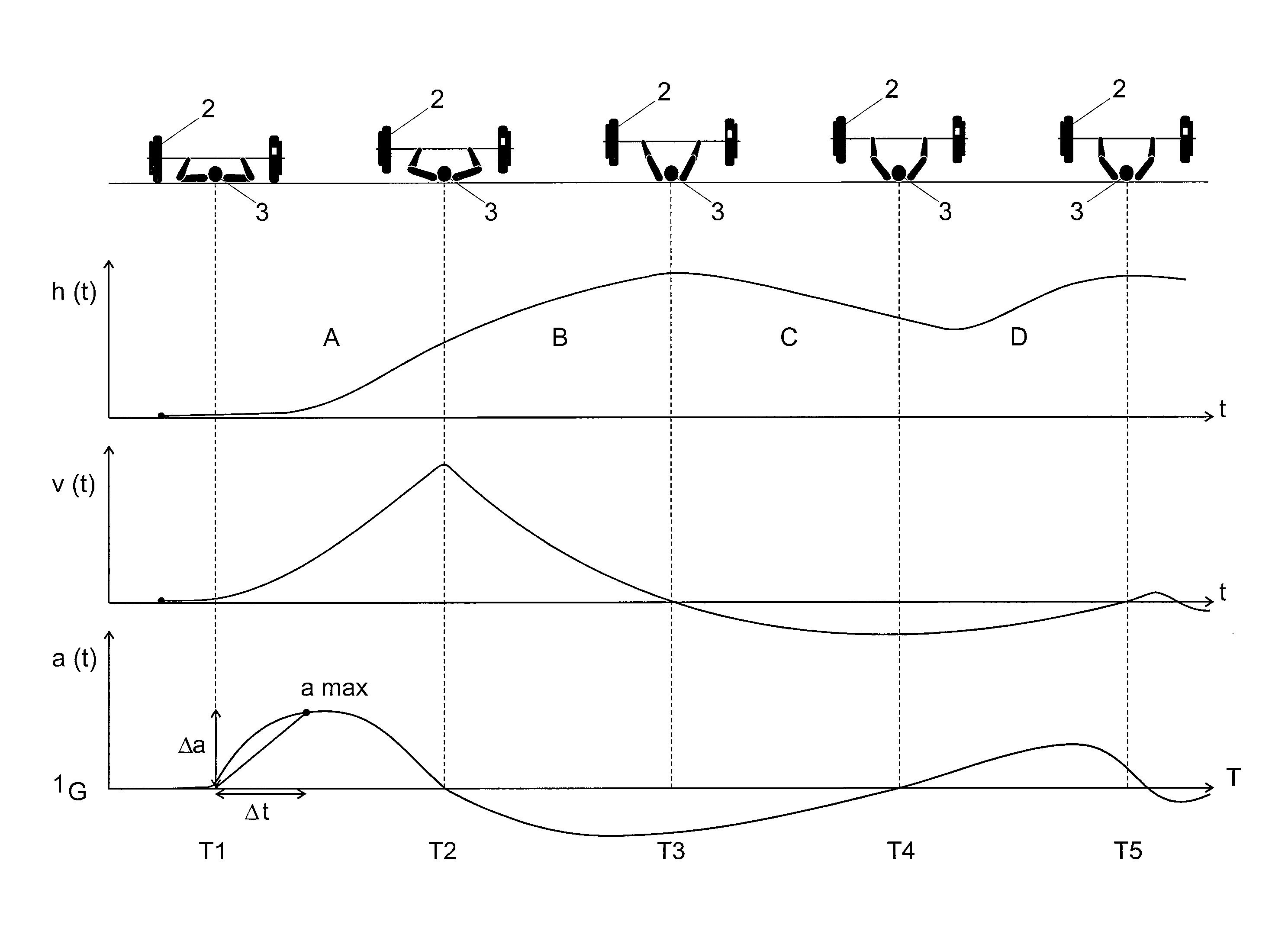
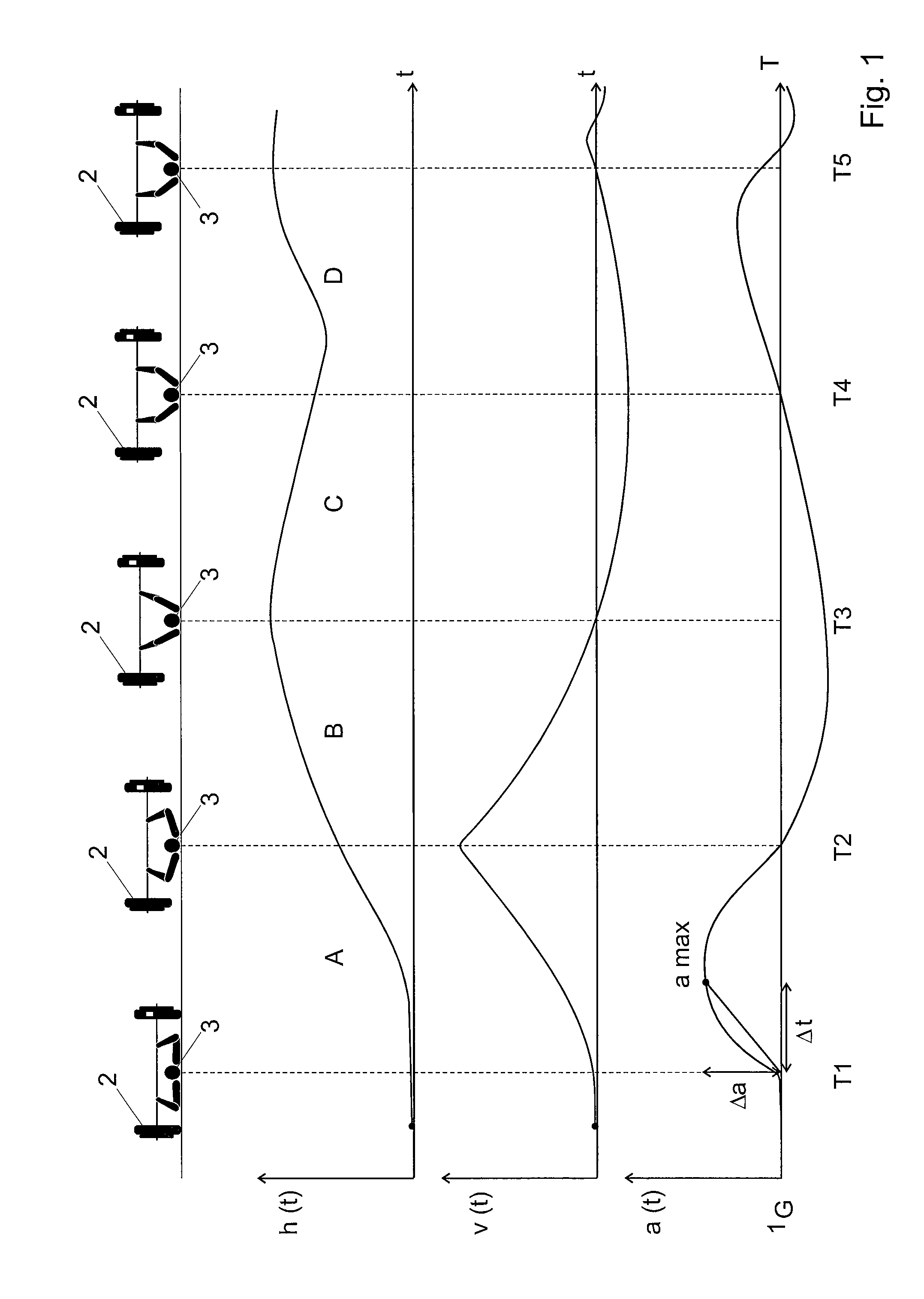
[0030]FIG. 1 illustrates the evolution of different kinematic parameters during a load-lifting movement of the type “bench-press”. This movement, often used in muscle training, consists in lifting a load 2 with both arms, from a position lying on the back. The load is lifted as high as possible by combining an adduction of the shoulder and an extension of the elbow. The upper line of FIG. 1 illustrates five phases of the movement. The exercise starts at T1, in the initial position represented on the first image on the left of FIG. 1. The load is at its lowest point (h(t)=0), the elbows of the athlete 3 are bent.

[0031]During phase A, between the instants T1 and T2, the athlete 3 lifts the load whose speed v(t) and height h(t) increase constantly, as indicated on the corresponding graphs. The pushing force (proportional to the acceleration a(t)) exerted during this phase is at its maximum and the arms extend.

[0032]During phase B, between the instants T2 and T3, the pushing continues b...


PUM


Abstract

Method enabling an athlete (3) performing a muscular training exercise to determine a setpoint for the rate of displacement of the displaced mass (2), comprising the following steps: 1) determining at least one initial setpoint rate at which said mass has to be displaced; 2) during the athlete's training exercise, measuring a series of acceleration values (a(n)) using a portable accelerometer (30) according to the displacements of said mass; and 3) depending on said series of acceleration values, having said portable accelerometer calculate at least one modified setpoint rate.

Description

RELATED APPLICATIONS[0001]The present invention is a continuation of international application PCT / EP2009 / 063916, filed on Oct. 22, 2009, the contents of which are enclosed by reference. It claims priority of Swiss Patent Application CH2008 / 01663, the contents of which are enclosed by reference.[0002]In some aspects, the present invention is also related to European Application EP2027817, filed on Aug. 8, 2008, and to European Application EP1834583, filed on Mar. 17, 2006.TECHNICAL FIELD[0003]The present invention concerns a method and device enabling an athlete to determine and then control the rate of displacement of a mass.TECHNICAL BACKGROUND[0004]There are many documents describing accelerometers for measuring sport performances. Most of the existing accelerometers are designed for exercises lasting for a long period of time, for example to evaluate the traveled distance or the calorie expenditure during a jogging session or a cycling tour. There are also fairly similar devices...

Claims


Application Information

Patent Timeline
Patent Type & Authority Patents(United States)
IPC IPC(8): A63B71/00
CPCA61B5/22A61B5/681A63B24/0062A61B5/4519A61B2562/0219A63B21/072A63B2220/20A63B2220/40A63B2244/09Y10S482/90
Inventor FLACTION, PATRICK
Owner SLYDE ANALYTICS LLC
Why Eureka
Try Eureka