
Hoisting method for overhauling and dismantling vaporization flue fixed at first section of converter

A technology for fixing vaporization and hoisting methods, applied in the direction of manufacturing converters, etc., can solve the problems of large dismantling work surface, prolong maintenance time, and dismantle many parts, and achieve the effect of reducing construction cost, reducing maintenance time, and improving efficiency and quality.

Active Publication Date: 2012-12-12
CHINA MCC17 GRP
View PDF3 Cites 19 Cited by
  • Summary
  • Abstract
  • Description
  • Claims
  • Application Information

AI Technical Summary

Problems solved by technology

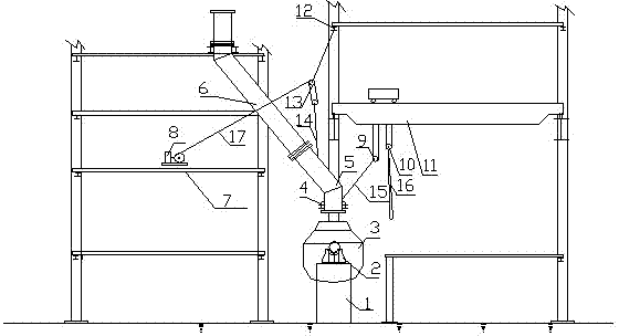
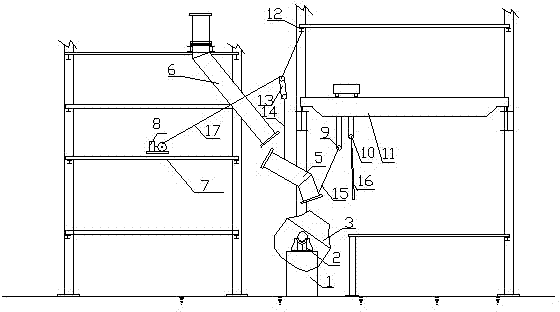
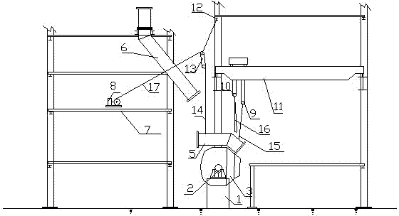
[0002] At present, in the metallurgical converter steelmaking, it is often encountered that the first fixed (i.e. the first fixed stage) vaporization flue needs to be replaced due to serious production wear, but the process platform and equipment layout in the converter area are many three-dimensional intersections. The fixed vaporization flue of the first stage is arranged between the movable vaporization flue of the converter and the fixed second stage vaporization flue, and the three-dimensional space is very compact and narrow. Usually, when replacing the first fixed vaporization flue, it is necessary to remove the support of the flue and the upper fixed II Part of the process platform affected by the first section of the vaporization flue and the hoisting ch

Method used


Image

  • Hoisting method for overhauling and dismantling vaporization flue fixed at first section of converter
  • Hoisting method for overhauling and dismantling vaporization flue fixed at first section of converter
  • Hoisting method for overhauling and dismantling vaporization flue fixed at first section of converter

Examples


Example Embodiment

[0035] Example

[0036] In a steelmaking plant’s 60t converter vaporization cooling flue removal and replacement project, the first section of the fixed vaporization flue is 13 meters long and weighs 10t, but the demolition area is very small, so the lifting method is used for construction, and the entire removal and lifting process The operation was smoothly implemented, and the time for the removal and replacement of the first fixed vaporization flue was advanced from 5 days to 3 days. The converter production resumed quickly, the effect was very obvious, the removal efficiency was high, and the product protection was good. The construction steps are:

[0037] 1. Set up lifting equipment:

[0038] 1) Set up a hoisting device:

[0039] Place a hoist 8 for driving the pulley block 13 on the second-layer platform 7 at the rear of the converter, and the power of the hoist 8 is 15kw;

[0040] 2) Set the pulley block:

[0041] The pulley block 13 is fixed on the oxygen lance platform beam ...


PUM


Abstract

The invention relates to a hoisting method for overhauling and dismantling a vaporization flue fixed at the first section of a converter, belonging to a hoisting device for equipment. The hoisting method comprises the following specific steps of: firstly, arranging a hoisting jig; secondly, arranging hoisting points and a hoisting steel wire rope; thirdly, dismantling a support seat; and fourthly, dismantling the vaporization flue fixed at the first section: (1) horizontal positioning: enabling the vaporization flue fixed at the first section to be horizontally placed on a body of the converter; (2) moving the vaporization flue fixed at the first section rightwards: enabling the vaporization flue fixed at the first section and the converter to commonly rotate and move rightwards to the inside of an adding bay of the converter; and (3) lifting the vaporization flue fixed at the first section: lifting a secondary lifting rope and a main lifting rope for an adding bay traveling crane, lifting the vaporization flue fixed at the first section and moving the adding bay traveling crane to hoist the vaporization flue fixed at the first section to the designated position to finish the dismantling and hoisting work. The efficiency and the quality for overhauling and dismantling the vaporization flue fixed at the first section of the converter are effectively improved, the construction cost is reduced and the overhaul time is shortened.

Description

technical field [0001] The invention belongs to an equipment hoisting method, in particular to a hoisting method for overhauling and dismantling a vaporization flue of a converter. Background technique [0002] At present, in the metallurgical converter steelmaking, it is often encountered that the first fixed (i.e. the first fixed stage) vaporization flue needs to be replaced due to serious production wear, but the process platform and equipment layout in the converter area are many three-dimensional intersections. The fixed vaporization flue of the first stage is arranged between the movable vaporization flue of the converter and the fixed second stage vaporization flue, and the three-dimensional space is very compact and narrow. Usually, when replacing the first fixed vaporization flue, it is necessary to remove the support of the flue and the upper fixed II Part of the process platform affected by the first section of the vaporization flue and the hoisting channel, as we...

Claims


Application Information

Patent Timeline
IPC IPC(8): C21C5/46
Inventor 朱道付陈玉洲
Owner CHINA MCC17 GRP
Learn More