Electromagnet assembly directly driving latch of an electronic circuit breaker

a technology of electronic circuit breakers and latches, applied in the direction of circuit breakers, protective switches, switches with electromagnetic release, etc., to achieve the effect of efficient magnetic attraction

Active Publication Date: 2012-04-17
SIEMENS IND INC
View PDF1 Cites 8 Cited by
  • Summary
  • Abstract
  • Description
  • Claims
  • Application Information

AI Technical Summary

Benefits of technology

[0018]These and other objects are achieved in accordance with the present invention by use of an electromagnet that attracts the latch. The electromagnet structure employs a reciprocating ferromagnetic core oriented proximal the latch, such as proximal a latch extension. Close proximity of the ferromagnetic core and latch enables efficient magnetic attraction of the latch to the electromagnet when the circuit breaker is tripped by the electronic fault detection circuit. However, the reciprocating core can be pushed by the latch or latch extension when the latch is pivoted by the electromechanical trip unit during detection and interruption of overcurrent or short circuit faults. Alternatively, the electromagnet may be constructed with a fixed core. In this alternative embodiment of the present invention, the electromagnet is oriented outside the swept volume of the latch. In another alternative embodiment of the present invention the electromagnet is oriented outside the swept volume of the latch and may be oriented radially tangential to a face of the latch extension. As the latch pivots about its pivot axis, the latch extension face sweeps an arc. The electromagnet is oriented laterally spaced away from the latch extension pivoting arc. In this configuration the electromagnet attracts the latch extension when energized by the electronic fault detection unit. However, when tripped by the electromechanical trip unit, the latch extension pivots laterally past the electromagnet.

Problems solved by technology

However, when tripped by the electromechanical trip unit, the latch extension pivots laterally past the electromagnet.

Method used


Image

  • Electromagnet assembly directly driving latch of an electronic circuit breaker
  • Electromagnet assembly directly driving latch of an electronic circuit breaker
  • Electromagnet assembly directly driving latch of an electronic circuit breaker

Examples


Embodiment Construction

[0040]After considering the following description, those skilled in the art will clearly realize that the teachings of the present invention can be readily utilized in circuit breaker trip units.

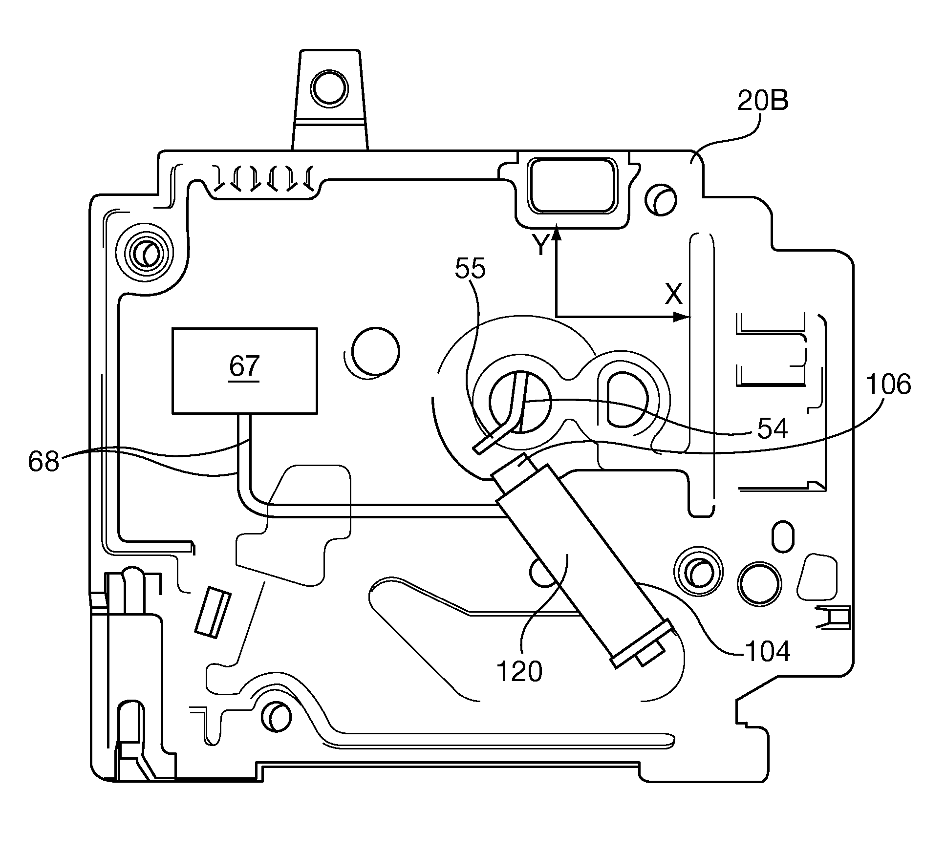
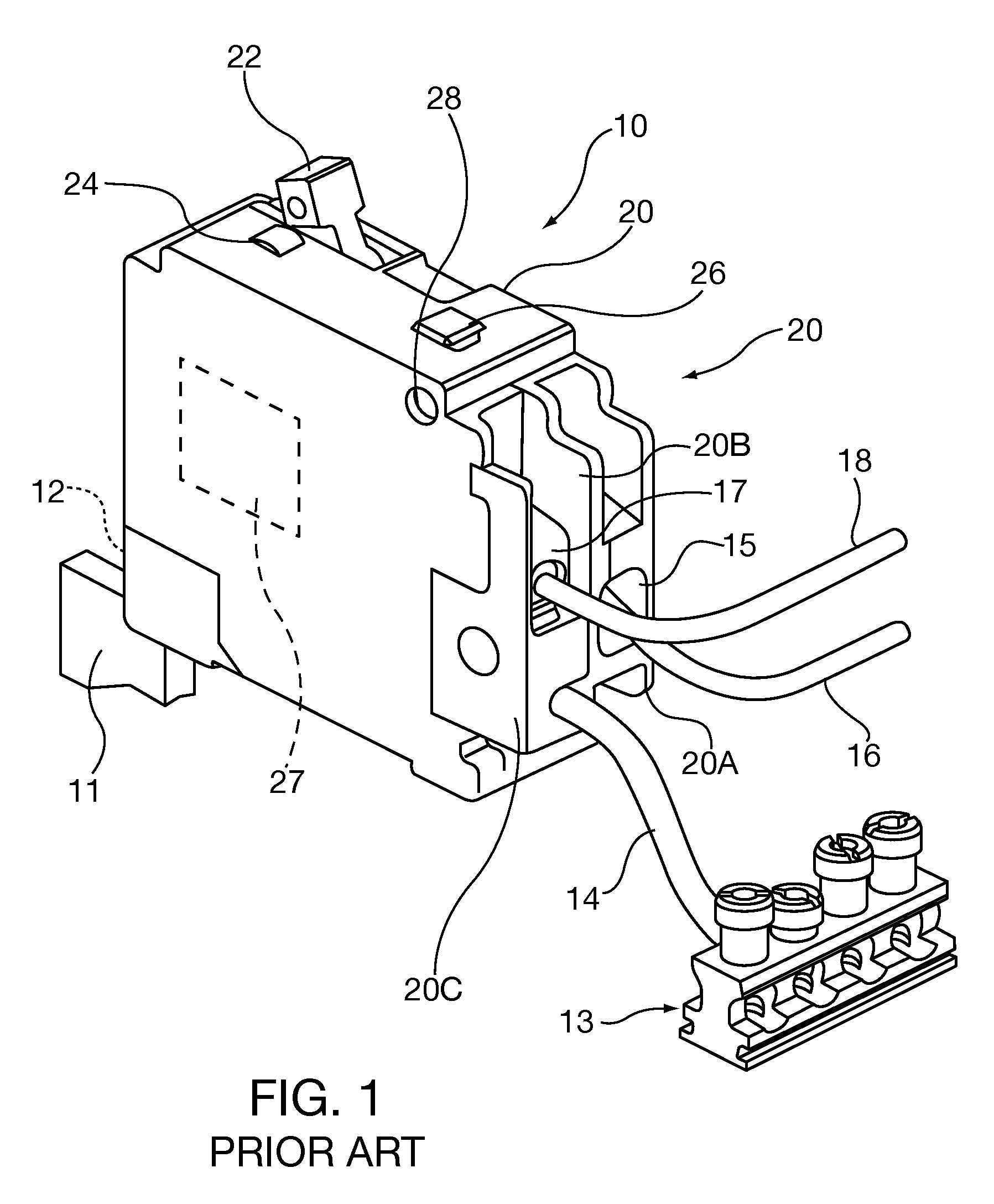
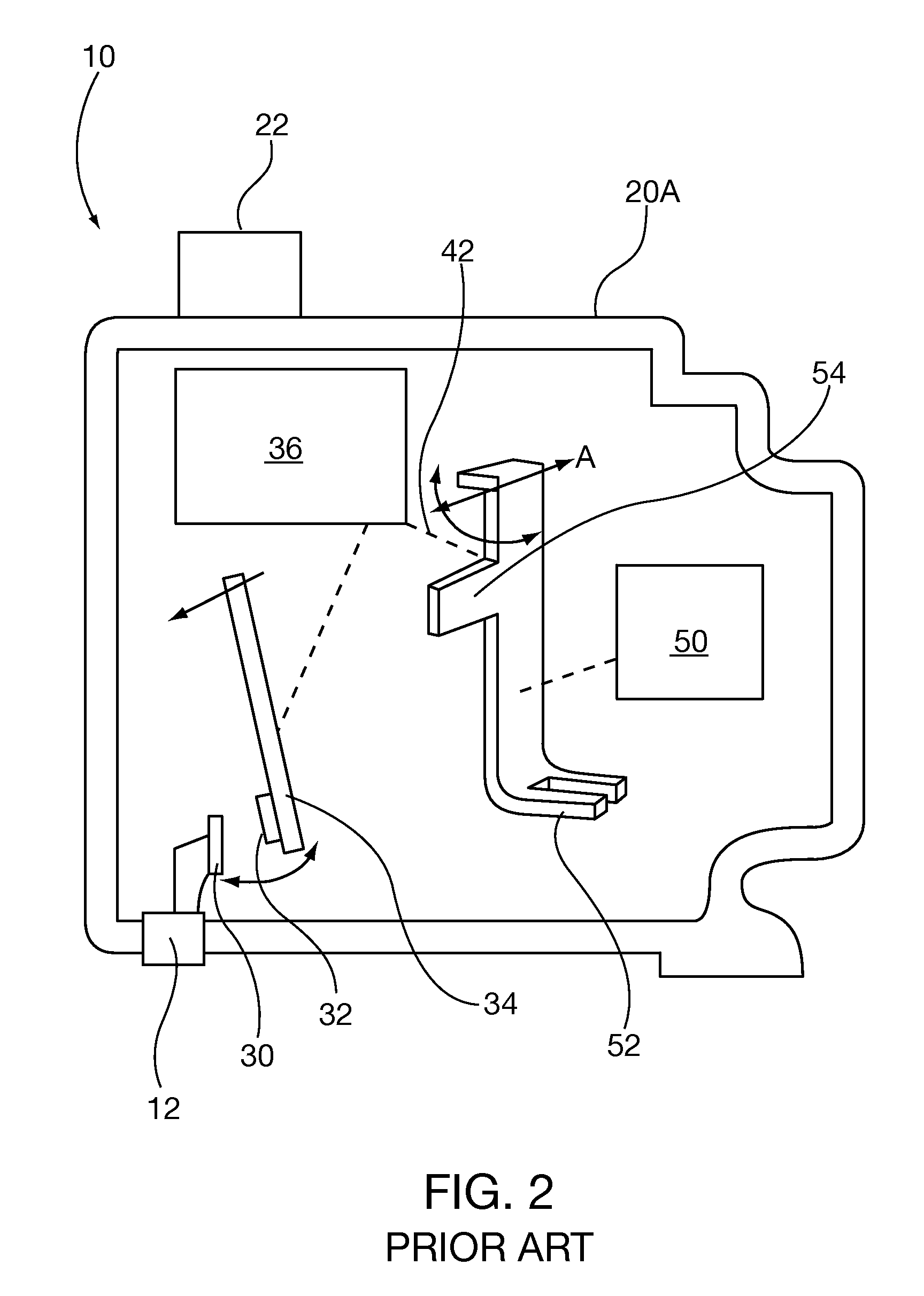
[0041]The general construction of the circuit breaker internal components shown in FIG. 6 are substantially similar to those of the prior art Siemens circuit breaker first compartment described with respect to FIGS. 1 and 2. As will be described in further detail herein, some embodiments of the latch 52 and latch extension 54, as well as the second compartment components of the circuit breaker of the present invention are different than those of the prior art second compartment embodiment shown in FIG. 3. While some of the exemplary circuit breaker embodiments described herein have two separate compartments, it is possible to package the internal components in a single compartment.

[0042]FIG. 6 is a perspective plan view of the first compartment of a circuit breaker 10 of the present inventio...


PUM


Abstract

A circuit breaker includes a trip unit and an electronic fault detection unit sharing a common trip latch for causing the circuit breaker to trip upon detection of a fault by either unit. The circuit breaker has an electromagnet for causing the circuit breaker to trip upon detection of a fault by an electronic fault detection unit. The electromagnet is oriented in the housing proximal the trip latch without any components interposed between them, and directly attracts the latch. Advantageously the electromagnet orientation does not impact operation or the range of motion of the latch or other trip unit components. Advantageously the circuit breaker of the present invention does not increase the trip latch mass, its bulk swept volume through its range of motion or require additional linkage components that potentially might increase trip cycle time. In some embodiments the electromagnet core is reciprocable.

Description

CLAIM TO PRIORITY[0001]This application claims the benefit of co-pending U.S. provisional patent application entitled “Electromagnet Assembly Directly Driving Latch of an Electronic Circuit Breaker” filed Sep. 22, 2008 and assigned Ser. No. 61 / 098,845, which is incorporated by reference herein.BACKGROUND OF THE DISCLOSURE[0002]1. Field of the Invention[0003]The invention relates to circuit breaker circuit protection devices for electrical distribution systems. More particularly the present invention is directed to latch mechanisms for tripping the operating mechanism of a circuit breaker in response to an actual fault detection made by either a thermal-magnetic electromechanical or electronic trip unit (or other electronic monitoring device) that operate independently within a circuit breaker. Alternatively the operating mechanism may be tripped in response to simulated fault detection in the distribution system.[0004]2. Description of the Prior Art[0005]Circuit breakers are utilize...

Claims


Application Information

Patent Timeline
Patent Type & Authority Patents(United States)
IPC IPC(8): H01H75/00H01H73/02
CPCH01H71/123H01H71/2463H01H71/16H01H71/2454
Inventor YANG, GUANGCOWANS, JOHN QUENTIN
Owner SIEMENS IND INC
Why Eureka
Try Eureka