

Intake air flow rate detection for internal combustion engine
a technology of internal combustion engine and intake air flow rate, which is applied in the direction of electrical control, process and machine control, instruments, etc., can solve the problem that the control is not always performed appropriately
- Summary
- Abstract
- Description
- Claims
- Application Information
AI Technical Summary
Benefits of technology
Problems solved by technology
Method used
Image

Examples
first embodiment
[0014]Referring to FIGS. 1-4 of the drawings, this invention will be described.
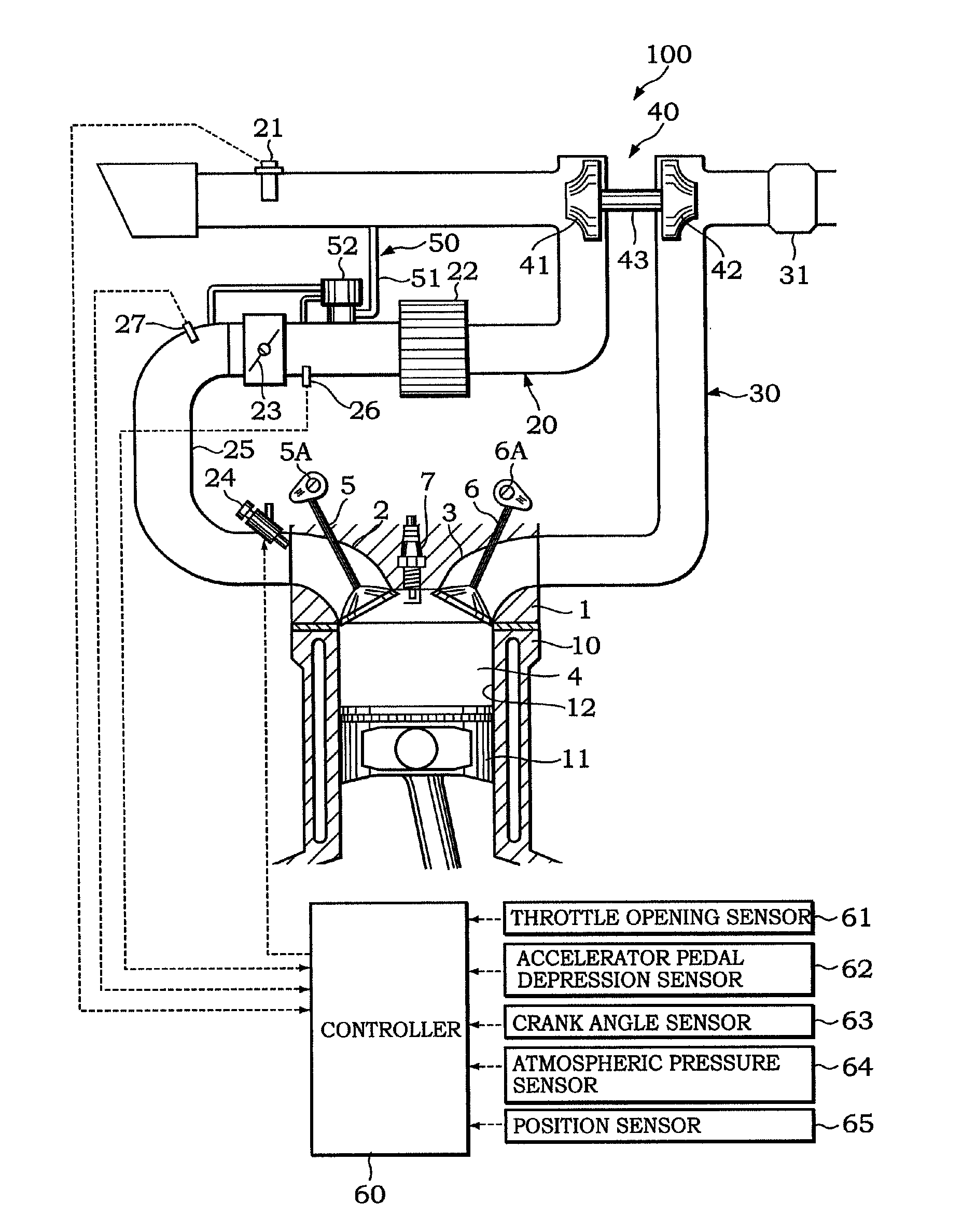
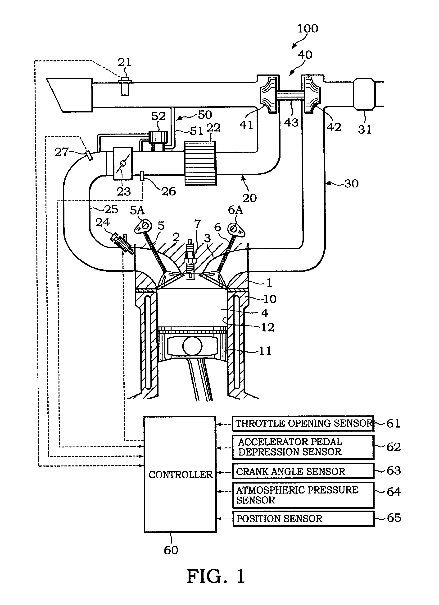
[0015]Referring to FIG. 1, an internal combustion engine 100 for a vehicle comprises a cylinder block 10, and a cylinder head 1 disposed on an upper side of the cylinder block 10.
[0016]A cylinder 12 accommodating a piston 11 is formed in the cylinder block 10. A combustion chamber 4 is formed by a crown surface of the piston 11, a wall surface of the cylinder 12, and a lower surface of the cylinder head 1. When an air-fuel mixture is burned in the combustion chamber 4, the piston 11 receives combustion pressure generated by the combustion, and as a result performs a reciprocating motion within the cylinder 12.
[0017]An intake port 2 that supplies the air-fuel mixture to the combustion chamber 4 and an exhaust port 3 that allows exhaust gas to flow out from the combustion chamber 4 are formed in the cylinder head 1.
[0018]An intake passage 20 supplies fresh air taken in from the outside to the intake port 2 ...
second embodiment
[0071]Referring to FIG. 5, this invention will be described.
[0072]The constitution of the internal combustion engine 100 according to the second embodiment is substantially identical to that of the first embodiment, but differs partially therefrom in the method of calculating the intake air flow rate when the bypass valve opening D is larger than the opening reference value D0. More specifically, limit values are set in relation to the intake air flow rate calculated on the basis of the detection signal from the air flow meter 21, and the following description will focus on this difference.
[0073]FIG. 5 is a flowchart showing an intake air flow rate calculation routine executed by the controller 60 of the internal combustion engine 100 according to the second embodiment. The intake air flow rate calculation routine is implemented together with the start of an engine operation, and is executed repeatedly at fixed intervals, for example periods of 10 milliseconds.
[0074]The control of s...
PUM
 Abstract
Description
Claims
Application Information