Livestock waterer

a waterer and livestock technology, applied in the field of livestock waterers, can solve the problems of complicated waterers, time-consuming, cost prohibitive, etc., and achieve the effect of preventing liquid from overflowing and constant liquid level

a waterer and livestock technology, applied in the field of livestock waterers, can solve the problems of complicated waterers, time-consuming, cost prohibitive, etc., and achieve the effect of preventing liquid from overflowing and constant liquid level

US8161907B2Inactive Publication Date: 2012-04-24DOUBLE C RANCH SUPPLY

Image

  • Livestock waterer
  • Livestock waterer

Examples


Embodiment Construction

[0011]In the following detailed description of the embodiments, reference is made to the accompanying drawings that form a part hereof, and in which are shown by way of illustration, and not by way of limitation, specific embodiments in which the invention may be practiced. It is to be understood that other embodiments may be utilized and that logical, mechanical and electrical changes may be made without departing from the spirit and scope of the present invention.

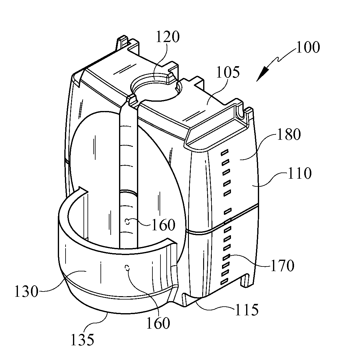
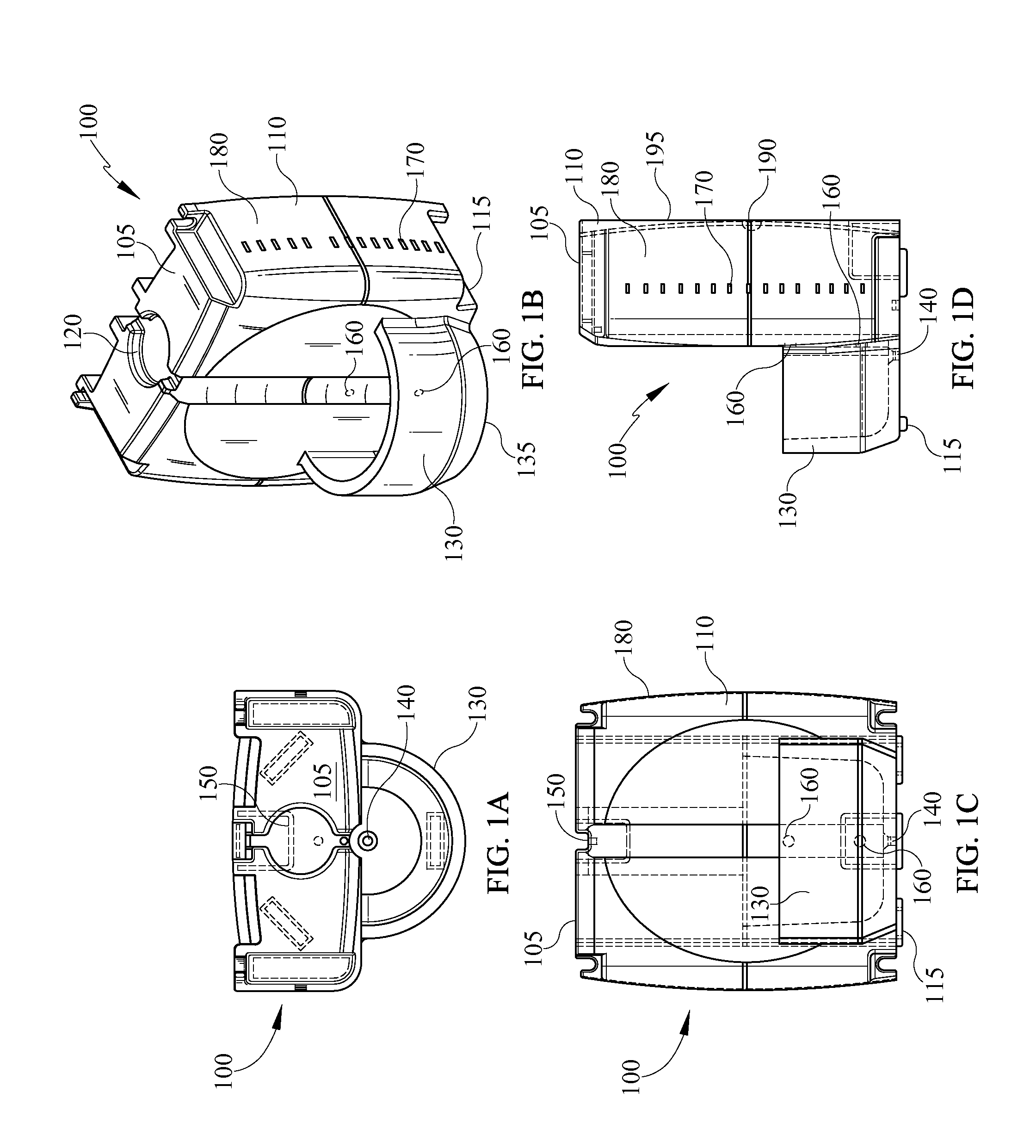
[0012]Referring initially to FIG. 1, a device designed to provide a continuous supply of water to livestock is illustrated. The device can be a livestock waterer 100. The waterer 100 is designed to safely and predictably provide at least one day's supply of water to large livestock, such as, for example, cattle and horses. The waterer 100 can also be used with smaller animals, such as, for example, sheep, pigs, goats, dogs, cats or any other domesticated animal. In one embodiment, the waterer 100 can be a one-piece molded...


PUM


Abstract

A device and method designed to provide a continuous supply of liquid to livestock is presented. The one-piece device comprises a storage tank and a drinking bowl. The storage tank can have a filling access hole for filling the tank. The tank can have at least one drinking bowl access hole which allows access from the tank to the bowl. Both the filling access hole and the drinking bowl access holes can be opened and closed. While filling, the drinking bowl access hole can be closed. After filling, the filling access hole can be closed and the drinking bowl access hole can be opened allowing liquid to flow from the tank into the bowl. Gravity and air pressure within the tank maintain a constant liquid level in the bowl while simultaneously preventing liquid from overflowing the bowl. A heating element can be placed into the tank to prevent freezing.

Description

CROSS-REFERENCE TO RELATED APPLICATIONS[0001]This application claims the benefit of U.S. Provisional Application Ser. No. 60 / 918,468, filed Mar. 16, 2007.BACKGROUND OF THE INVENTION[0002]The present invention relates, generally, to a livestock waterer and, in particular, to a simple, cost-effective livestock waterer that can provide at least a day's supply of water to an animal.[0003]Livestock waterers are commonly known in the art. However, typical waterers are geared towards large scale farms and ranches. These waterers tend to be complicated and require a dedicated water line and / or electrical lines which tends to be cost prohibitive to the small scale farmer, rancher and / or breeder. A typical small scale livestock owner uses a five gallon water bucket in each animal stall to provide water to the livestock. For example, a horse under average conditions typically consumes about fifteen gallons of water a day. Therefore, a water bucket for a typical horse on an average day must be ...

Claims


Application Information

Patent Timeline
24 Apr 2012
Publication
US8161907B2
IPC
A01K7/00
CPC
A01K7/02; A01K7/027
Inventors
CRAIG, CORY MICHAEL