Artificial heart pump with adjustable magnetic thrust bearing

a technology of magnetic thrust bearing and artificial heart pump, which is applied in the direction of piston pump, positive displacement liquid engine, prosthesis, etc., can solve the problems of generating abrasion powder, blood clot and destruction of red blood cells, and difficulty in controlling the dimensions by the above-mentioned machining, so as to achieve and easy adjustment of magnetic force of repulsion

Inactive Publication Date: 2012-05-01
MITSUBISHI HEAVY IND LTD
View PDF22 Cites 35 Cited by
  • Summary
  • Abstract
  • Description
  • Claims
  • Application Information

AI Technical Summary

Problems solved by technology

Therefore, there are possibilities of generating abrasion powders due to the contact of the rotor with the fixed bodies and of causing a blood clot and destruction of red blood cells.
In consequence, in order to optimize the dimensions of the clearances between the rotor and the fixed bodies, it is necessary to provide machining to the rotor and the fixed bodies, respectively, for the purpose of installing the permanent magnets, and it is difficult to control the dimensions by the aforementioned machining.

Method used


Image

  • Artificial heart pump with adjustable magnetic thrust bearing
  • Artificial heart pump with adjustable magnetic thrust bearing
  • Artificial heart pump with adjustable magnetic thrust bearing

Examples


first embodiment

[First Embodiment]

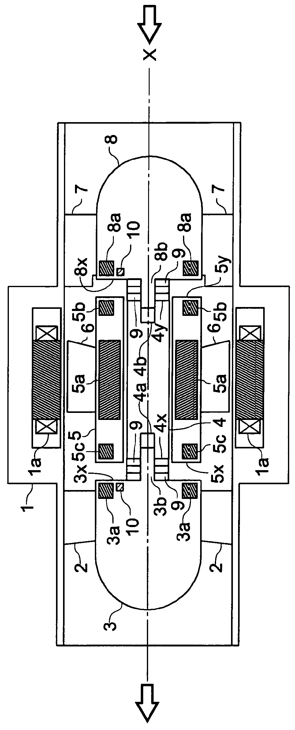
[0051]Referring to the drawings, a first embodiment of the present invention will be described hereinafter. FIG. 1 is a cross-sectional view showing a construction of an artificial heart pump in accordance with this embodiment of the present invention. Hereinafter, the words “before / anterior” and “after / posterior” will be referred as the anterior side (upstream-side) and the posterior side (downstream-side) respectively, in accordance with the flow of the blood.

[0052]An artificial heart pump in FIG. 1 comprises a cylindrical housing 1; a plurality of diffusers 2 being connected to the inside wall surface of the housing 1; a fixed body 3 being supported by the housing 1 by having a plurality of diffusers 2 protrude from the outside wall surface; a fixed shaft 4 being installed before the fixed body 3; a sleeve 5 being installed circularly around the fixed shaft 4 and rotating around the outer circumference of the fixed shaft 4; a plurality of blades 6 protruding fro...

second embodiment

[Second Embodiment]

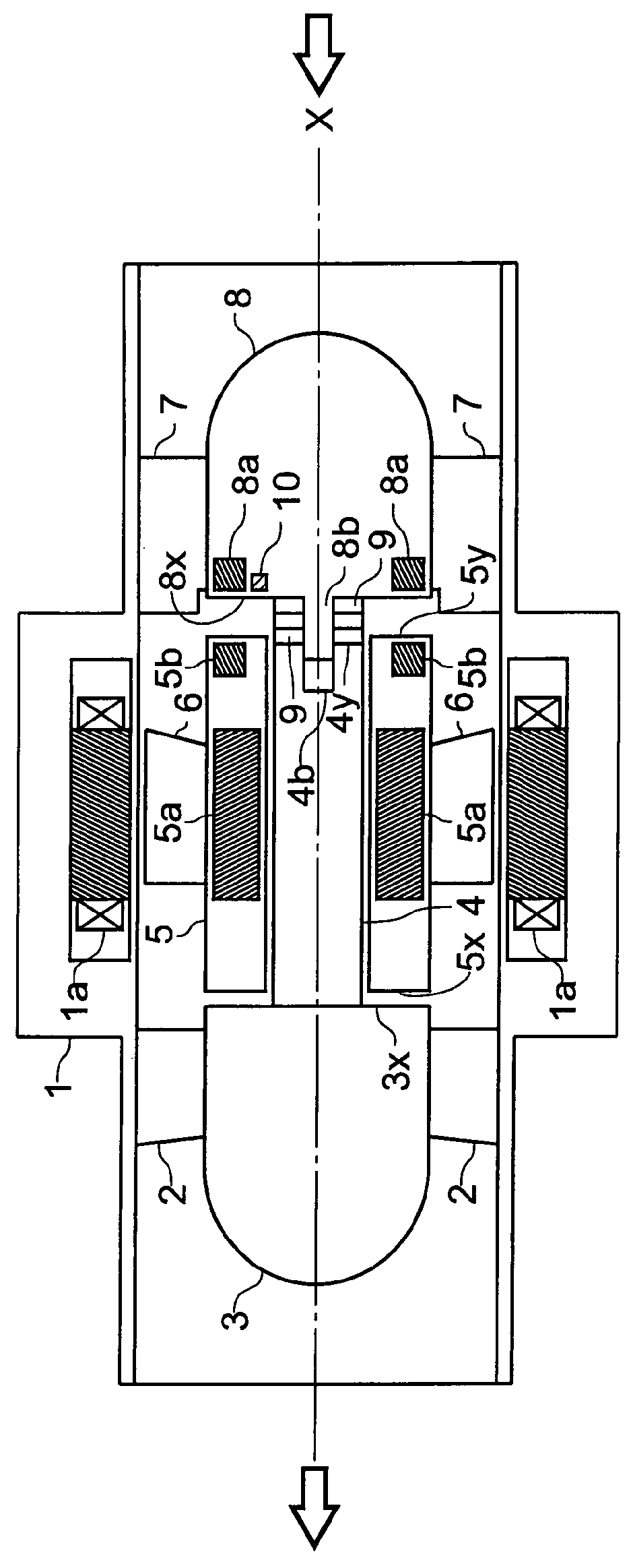
[0063]Referring to the drawings, a second embodiment of the present invention will be described hereinafter. FIG. 2 is a cross-sectional view showing a construction of an artificial heart pump in accordance with the present embodiment. In FIG. 2, same portions as in FIG. 1 will be provided with same symbols and the detailed description thereof will be omitted.

[0064]An artificial heart pump in FIG. 2 has a same construction as the artificial heart pump in FIG. 1, wherein permanent magnets 5c and 3a are excluded; and the construction that can be adjusted by the adjustment rings 9 is only provided in the part of the fixed body 8. To be specific, by having the clearances between the fixed bodies 3 and 8 and the sleeve 5 adjusted by the quantity and the thickness of the adjustment rings 9 that are installed circumferentially around the protruding portion 8b being provided to the fixed body 8, the magnetic forces of repulsion of the permanent magnets 5b and 8a are adjus...

third embodiment

[Third Embodiment]

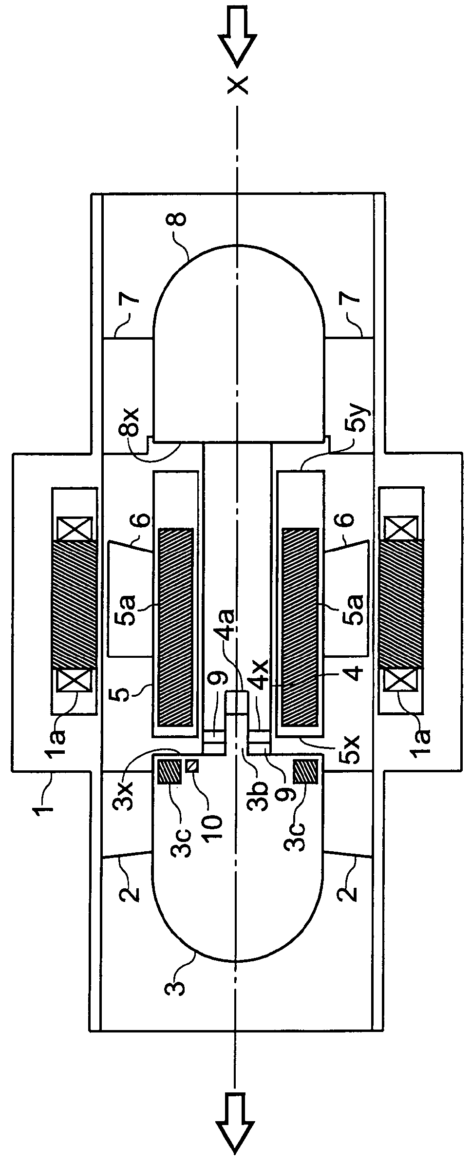
[0067]By referring to the drawings, a third embodiment of the present invention will be described hereinafter. FIG. 3 is a cross-sectional view showing a construction of an artificial heart pump in accordance with the present embodiment. In FIG. 3, same portions as in FIG. 1 will be provided with same symbols and the detailed description thereof will be omitted.

[0068]The artificial heart pump in FIG. 3 has a magnetic body 3c installed to the position where the permanent magnet 3a is installed, instead of having the permanent magnets 3a, 5b, 5c and 8a installed in the artificial heart pump that is constructed as shown in FIG. 1; utilizes the suction powers of the magnetic body 3c and the multi-pole oriented anisotropic permanent magnet 5a as the function of the thrust bearings; and has only the fixed body 3 constructed in a manner that adjustment by using the adjustment rings 9 is possible. To be specific, by adjusting the clearances between the fixed bodies 3 and 8...


PUM


Abstract

In order to optimize the clearances between both end surfaces of a sleeve 5 and each of the end surfaces of the fixed bodies 3 and 5, respectively, magnetic forces of repulsion being caused by each of the permanent magnets 3a, 5b, 5c and 8a is adjusted. At this time, by adjusting each of the distances between the permanent magnets 3a, 5b, 5c, 8a, respectively, by adjusting the quantity of the adjustment rings 9, the magnetic force of repulsion being caused by each of the permanent magnets 3a, 5b, 5c and 8a is adjusted.

Description

BACKGROUND OF THE INVENTION[0001]1. Field of the Invention[0002]The present invention relates to an artificial heart pump and especially relates to an artificial heart pump employing an axial-flow turbo pump that pumps the blood.[0003]2. Description of the Related Art[0004]Conventionally, an artificial heart pump which pumps the blood by utilizing the rotation of the impellers is employed as an alternate being used for medical purposes or as an assist pump. An artificial heart pump utilizing a roller pump or a centrifugal pump and an artificial heart pump utilizing an axial-flow turbo pump are provided as the aforementioned artificial heart pump. Among these various types of artificial heart pumps, the artificial heart pump utilizing an axial-flow turbo pump can reduce the size thereof, being compared with the artificial heart pump utilizing a roller pump or a centrifugal pump.[0005]The conventional artificial heart pump utilizing an axial-flow turbo pump has a housing thereof house...

Claims


Application Information

Patent Timeline
Patent Type & Authority Patents(United States)
IPC IPC(8): F04B35/04
CPCA61M1/101F04D3/00F04D29/041F04D29/047F04D29/048A61M1/1015A61M1/1031F04D29/0413A61M60/824A61M60/82A61M60/422A61M60/148A61M60/812A61M60/237
Inventor HIDAKA, TATSUYAKAKIUCHI, YOHEIOKUBO, TAKESHIOSADA, TOSHIYUKI
Owner MITSUBISHI HEAVY IND LTD
Why Eureka
Try Eureka