Electrically driven motors and pumps having such motors

a technology of electric motors and motors, which is applied in the direction of positive displacement liquid engines, pumping machines, machines/engines, etc., can solve the problems of a large number of parts and a limitation in the attempt to downsize the motors

Inactive Publication Date: 2005-04-07
AISAN IND CO LTD
View PDF5 Cites 60 Cited by
  • Summary
  • Abstract
  • Description
  • Claims
  • Application Information

AI Technical Summary

Benefits of technology

[0007] It is accordingly an object of the present invention to teach improved techniques for minimizing the number of parts and the number of assembly steps of electrically driven motors.

Problems solved by technology

Because the motor of the above publication requires a spring to bias the rotor toward the thrust bearing, there has been a problem with the relatively large number of parts and the relatively large number of assembly steps for assembling the motor.
These problems have been a limitation in attempts to downsize the motors.

Method used


Image

  • Electrically driven motors and pumps having such motors
  • Electrically driven motors and pumps having such motors
  • Electrically driven motors and pumps having such motors

Examples


first representative embodiment

[0027] First Representative Embodiment

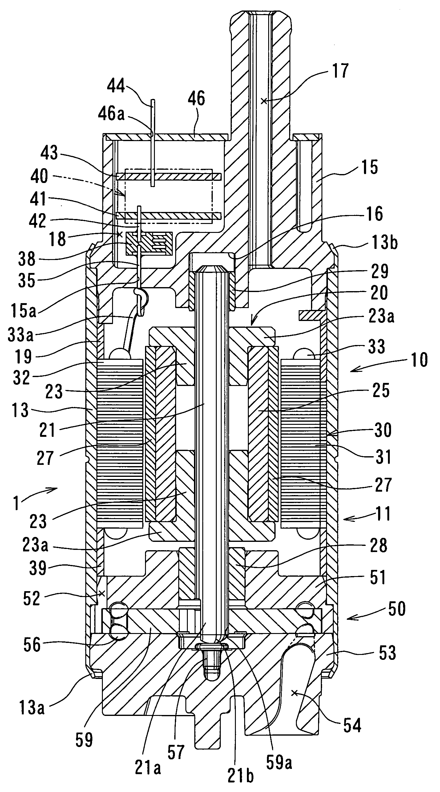
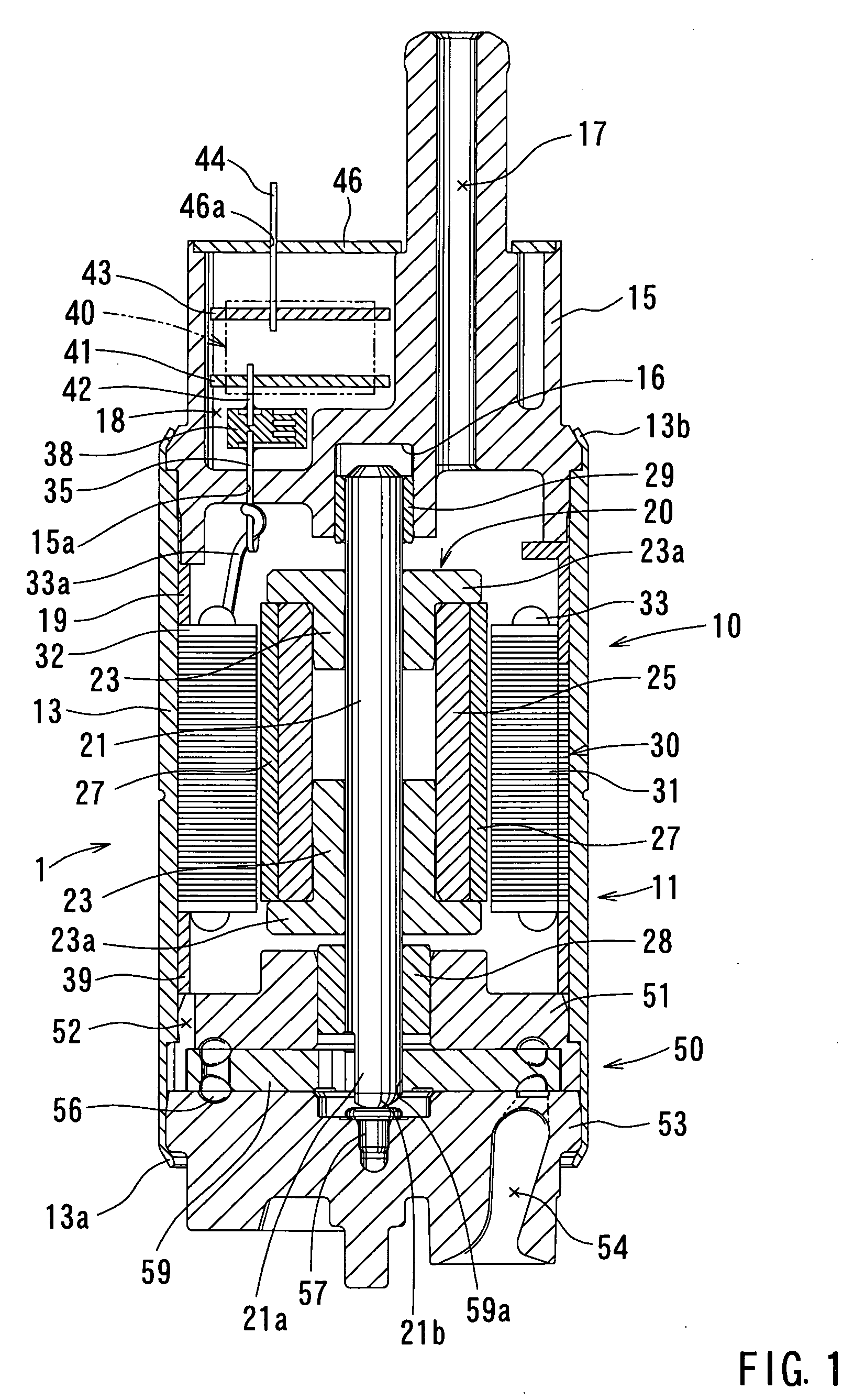
[0028] Referring to FIG. 1, a fuel pump 1 according to a first representative embodiment is mountable on an automobile (not shown) and has a brush-less DC motor as a motor section 10. As shown in a vertical sectional view in FIG. 1, the fuel pump 1 includes a pump section 50 in addition to the motor section 10. The pump section 50 is disposed on the lower side of the motor section 10.

[0029] The motor section 10 will now be described. The motor section 10 generally includes a housing 11, a rotor 20 rotatably supported within the housing 11, and a stator 30 fixedly mounted within the housing 11. The housing 11 has a substantially cylindrical housing tube 13, an upper end cover 15 mounted to the upper end of the housing tube 13, and a pump casing 51 and a pump cover 53 mounted to the lower end of the housing tube 13. An axial support hole 16 is formed in an inner wall of the upper end cover 15 (the lower wall as viewed in FIG. 1) and extends subst...

second representative embodiment

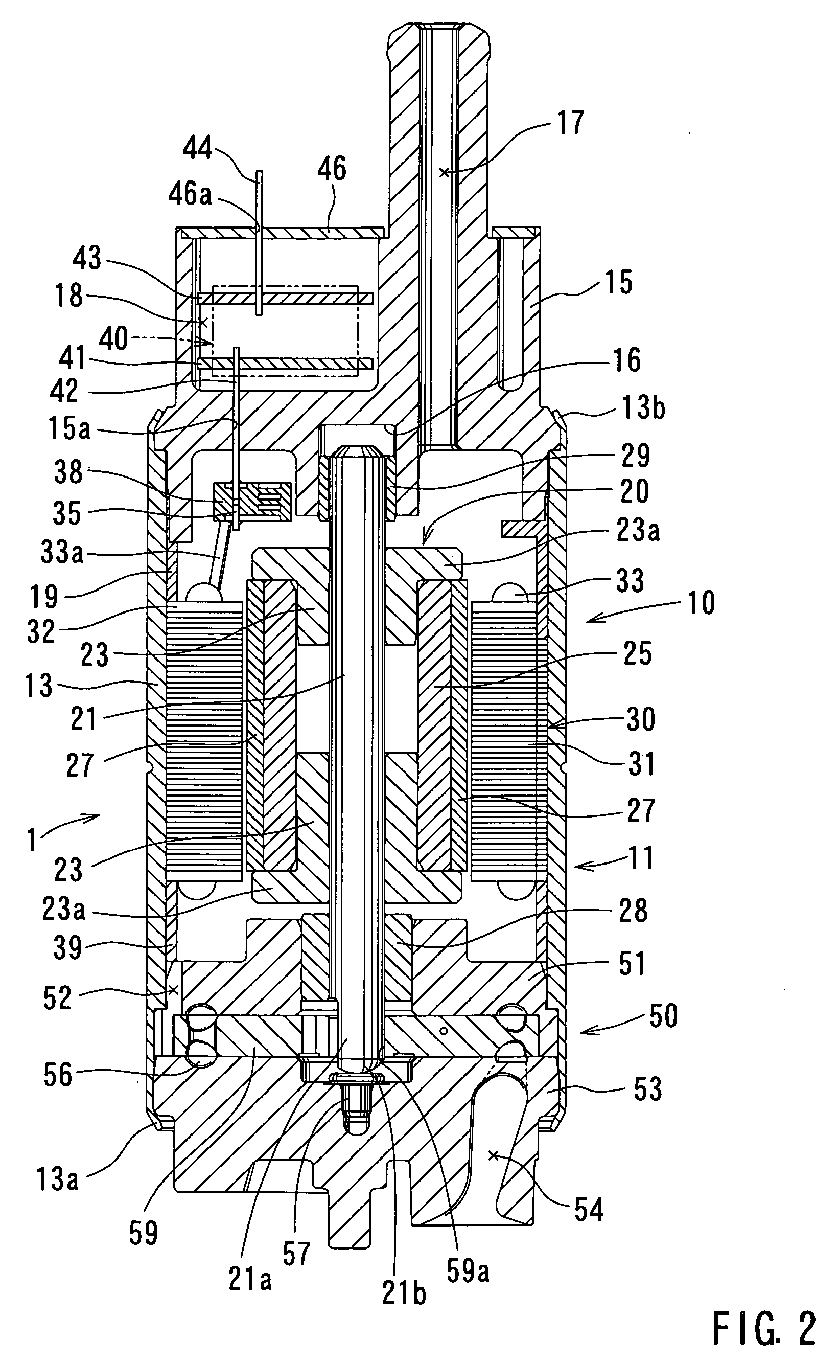
[0047] Second Representative Embodiment

[0048] The second representative embodiment will now be described with reference to FIG. 2. The second representative embodiment is different from the first representative embodiment only in that the connecting circuit board 38 is disposed within the housing 11. Therefore, the connecting circuit board 38 is connected to the terminal 35 at a location within the housing 11. In this case, the connecting terminal 42 of the coil-side circuit board 41 extends through the terminal hole 15a formed in the upper end cover 15 so as to be electrically connected to the connecting circuit board 38. Also with this second representative embodiment, substantially the same operation and advantages may be attained as with the first representative embodiment.

third representative embodiment

[0049] Third Representative Embodiment

[0050] The third representative embodiment will now be described with reference to FIG. 3. The third representative embodiment is different from the first representative embodiment in that the housing tube 13 and the upper end cover 15 of the housing 11 are molded integrally with each other into an integral housing member 12 via a resin molding process. In addition, the upper spacer 19 and the lower spacer 39 are also molded integrally with the housing member 12. Further, the stator 30, including the terminal end 33a of the stator coil 33 connected to the terminal 35, is integrated within the housing tube 13, i.e., the housing member 12, using an insertion molding process. For example, the stator 30 may be set into a cavity of the mold used for molding the housing member 12. A resin material may then be injected into the cavity, consequently integrating the stator 30 with the housing member 12. FIG. 4 shows a vertical sectional view of the stato...


PUM


Abstract

A motor, possibly for a pump, has a housing, a first member disposed within the housing and mounted on an inner wall of the housing, and a second member rotatably disposed within the housing and having a rotary shaft. A thrust bearing is mounted within the housing in order to support a first end of the rotary shaft in an axial direction of the rotary shaft. A core and coils wound around the core are provided on one of the first and second members. A set of magnets is provided on the other of the first and second members. The core and the set of magnets are positioned such that a magnetic force is produced in an area where a magnetic flux is generated between the core and the set of magnets. The magnetic force causes the second member to move toward the thrust bearing.

Description

[0001] This application claims priority to Japanese patent application serial number 2003-344431, the contents of which are incorporated herein by reference. BACKGROUND OF THE INVENTION [0002] 1. Field of the Invention [0003] The present invention relates to electrically driven motors and pumps having such motors. [0004] 2. Description of the Related Art [0005] Various types of electrically driven motors are known. For example, Japanese Laid-Open Patent Publication No. 2000-102210 teaches a brush-less electrically driven motor having a housing, a stator, a rotor, magnets, a thrust bearing, and a spring. The rotor has a rotor shaft that is rotatably supported by the housing. The magnets are provided on the rotor and oppose the stator via a predetermined space. The thrust bearing is mounted to the housing and supports the one end of the rotor shaft with respect to a thrust direction. The spring biases the rotor in a direction toward the thrust bearing, so that the one end of the rotor...

Claims


Application Information

Patent Timeline
Patent Type & Authority Applications(United States)
IPC IPC(8): H02K29/00F04D5/00H02K5/12H02K5/15H02K5/167H02K5/24H02K7/08H02K7/14H02K21/12H02K21/16
CPCF04D5/002H02K5/12H02K21/16H02K5/1672H02K7/083H02K5/15H02K7/14H02K21/12
Inventor NAITO, HIROAKI
Owner AISAN IND CO LTD
Why Eureka
Try Eureka