Ophthalmic display

a technology of ophthalmic display and display screen, which is applied in the field of ophthalmic display, can solve the problems of significant play between rods and slideways, prejudicious to display accuracy, and limited production, so as to achieve quick and easy operation, minimize the number of parts used, and preserve positioning accuracy

Inactive Publication Date: 2010-06-10
ESSILOR INT CIE GEN DOPTIQUE
View PDF2 Cites 3 Cited by
  • Summary
  • Abstract
  • Description
  • Claims
  • Application Information

AI Technical Summary

Benefits of technology

[0019]The advantage of this type of solution resides in its suitability for fastening a light-beam generator system on an information lens or eyeglass lens subject to significant constraints in mechanical, optical, bulk, weight, and appearance terms.
[0020]The number of parts used is minimized. Use takes place without actuating any external tool, quickly and easily. The absence of rubbing parts ensures that positioning accuracy is preserved. In terms of appearance, the residual parts on the information eyeglass lens, namely the two hooks, are very discrete. The general bulk of the connection system is minimal, as much in the light-beam generator system as on the lens. The contribution to the total weight is minimal given that the parts dedicated solely to fastening are the hooks.

Problems solved by technology

That type of connection and focus-adjuster device poses the following technical problems.
This can lead to a constraint in its production.
That type of device inevitably leads to significant play between rods and slideways, and that is prejudicial to the accuracy of the display.
This results in rapid wear of the casing, further increasing play, and consequently increasing the inaccuracy of the display.
It goes without saying that such an arrangement is not very accurate, not very comfortable to use, and is poorly adapted to everyday use as opposed to experimental use.

Method used


Image

  • Ophthalmic display
  • Ophthalmic display
  • Ophthalmic display

Examples


Embodiment Construction

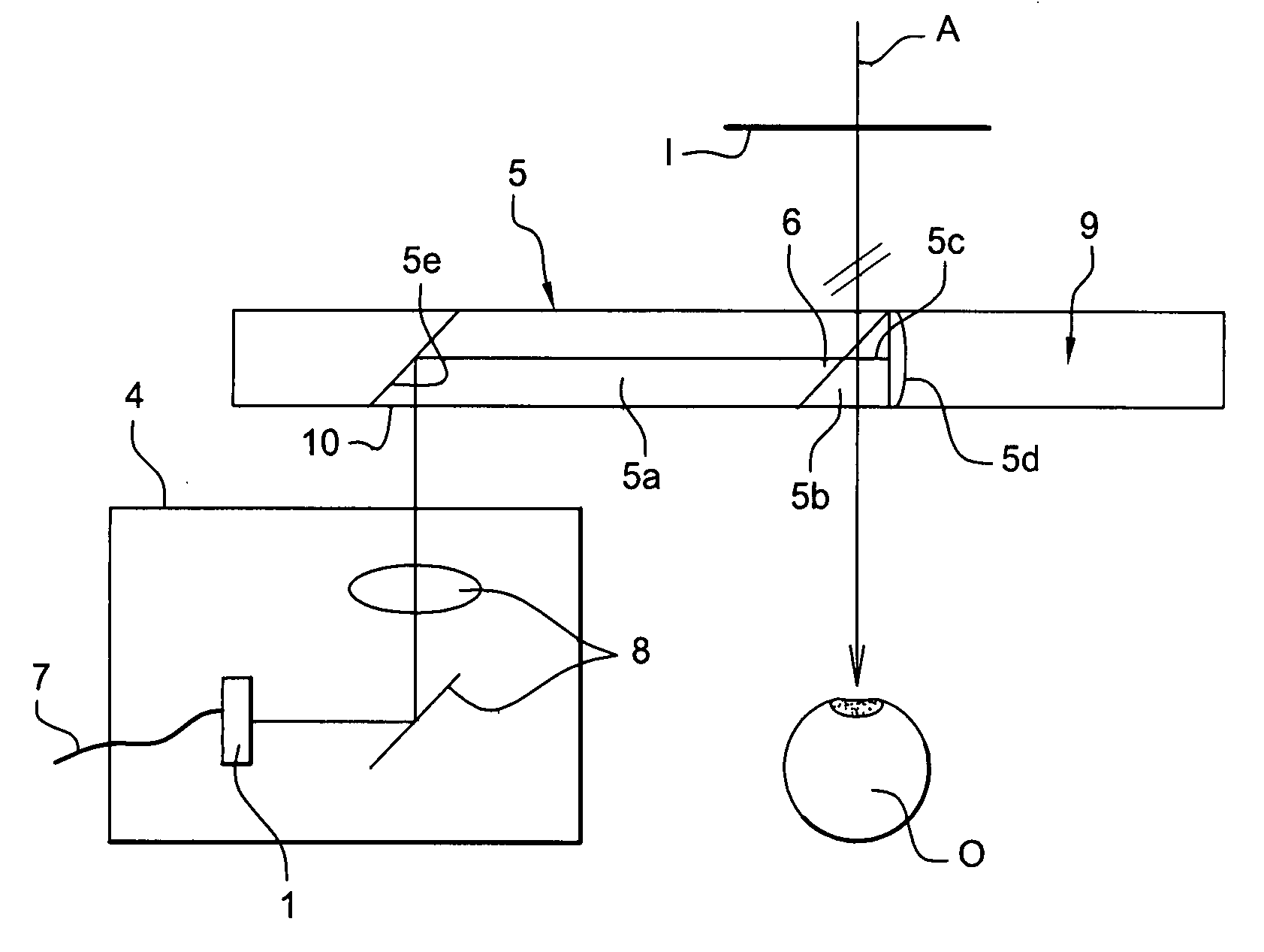
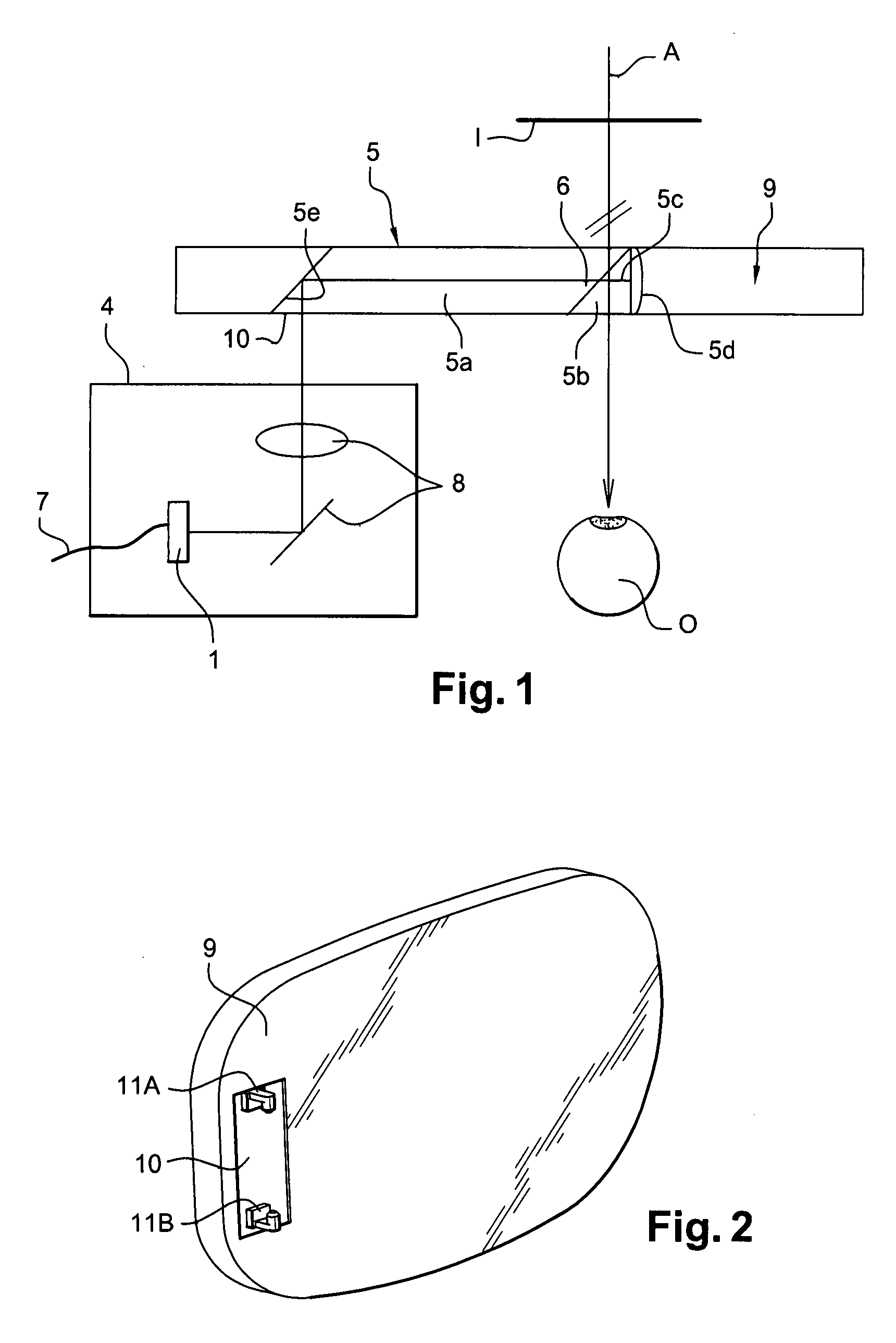
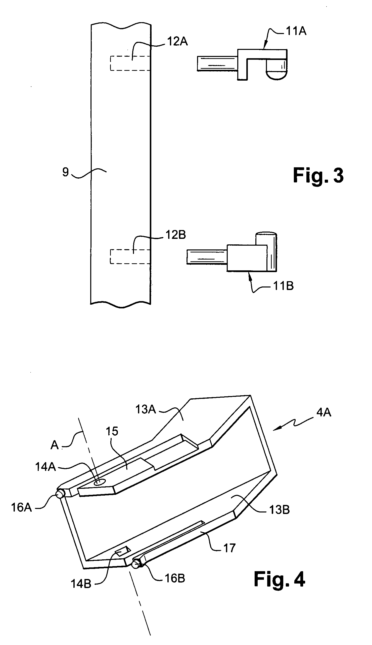
[0044]FIGS. 2 and 3 show a lens 9 that is constituted by an optionally-corrective lens for mounting in an eyeglass frame. As shown in FIG. 1, an optical imager 5 is inserted in the lens 9, with only the inlet face 10 for the light beams being visible in FIG. 2. The light beams are emitted by a miniature screen of a light-beam generator system 4 that is shown in FIGS. 4 and 5.

[0045]An adapter is in a reference position relative to the imager, i.e. is secured to the imager or to the lens, in accurate manner, in order to ensure that the light beams are transmitted in correct and optimum manner inside the imager, and in order to ensure that they are propagated towards the eye O of the wearer, so as to make it possible to view an image I. The adapter is constituted by two snap-fastener hooks 11A, 11B that are anchored in bores 12A, 12B that are arranged in the inlet face 10 of the imager that is inserted in the lens 9, e.g. by being embedded therein.

[0046]It is possible to envisage makin...


PUM

PropertyMeasurementUnit
sizeaaaaaaaaaa
voltageaaaaaaaaaa
voltageaaaaaaaaaa

Abstract

The invention relates to an ophthalmic display comprising an optical imager both for shaping light beams emitted by a miniature screen of a light-beam generator system for generating light beams that are introduced into said imager via an inlet face, and for directing them towards the eye of the wearer so as to make it possible to view an image, an adapter being in a reference position relative to the imager, and said light-beam generator system including a connection arrangement for connection to said adapter, the connection between said system and said adapter being releasable. In the invention, said adapter is constituted by two snap-fastener hooks for housing in housings carried by said connection arrangement.

Description

[0001]The present invention relates to an ophthalmic display comprising an optical imager that makes it possible to project information of the image or multimedia type, and that is preferably associated with a lens. The term “lens” is used herein to designate an optical system that can, in particular, be positioned in an eyeglass frame.BACKGROUND OF THE INVENTION[0002]It is known from U.S. Pat. No. 5,886,822 to make an ophthalmic lens that presents a projector insert. Such a projector insert is constituted by an optical imager for shaping the light beams coming from an electronic and optical light-beam generator system of the miniature screen, laser diode, or light-emitting diode type, for generating light beams from an electronic signal. The optical imager directs the light beams towards the eye of the wearer so as to make it possible to view the information content.[0003]An example of a known display is shown diagrammatically in greater detail in FIG. 1.[0004]By way of example, th...

Claims


Application Information

Patent Timeline
Patent Type & Authority Applications(United States)
IPC IPC(8): G09G5/00G02F1/01G02F1/13
CPCG02B27/0149G02B2027/0132G02B2027/0127G02B27/0176G02B27/021G02B2027/0178
Inventor MOLITON, RENAUDBONAFOS, CECILEROUSSEAU, BENJAMIN
Owner ESSILOR INT CIE GEN DOPTIQUE
Why Eureka
Try Eureka