Flat luminescent lamp and method for manufacturing the same

a luminescent lamp and flat technology, applied in the field of luminescent lamps, can solve the problems of inefficient back light, increased weight, power consumption, thickness of the device, etc., and achieve the effect of reducing manufacturing costs, minimizing process steps, and minimizing parts

Active Publication Date: 2006-07-18
LG DISPLAY CO LTD +2
View PDF6 Cites 3 Cited by
  • Summary
  • Abstract
  • Description
  • Claims
  • Application Information

AI Technical Summary

Benefits of technology

[0023]An object of the present invention is to provide a flat luminescent lamp and a method for manufacturing the same, in which the number of parts is minimized to minimize the process steps, thereby reducing the manufacturing cost.

Problems solved by technology

The back light is inefficient because it increases the weight, power consumption, and thickness of the device.
As a result, it is difficult to form a LCD back light with a very thin size.
This also makes it difficult to form a thin sized back light for LCD devices.
In this case, since the fluorescent lamp is mounted at one side and light passes through the light-guiding plate, luminance becomes too low.
However, the related art flat luminescent lamp has several problems.
Since four frames and a number of the support rods are required to seal the lower and upper substrates, the number of parts for manufacturing the lamp increases and the process steps become complicated.
This also leads to the increased weight and volume of the lamp.

Method used


Image

  • Flat luminescent lamp and method for manufacturing the same
  • Flat luminescent lamp and method for manufacturing the same
  • Flat luminescent lamp and method for manufacturing the same

Examples


Embodiment Construction

[0040]Reference will now be made in detail to the preferred embodiments of the present invention, examples of which are illustrated in the accompanying drawings.

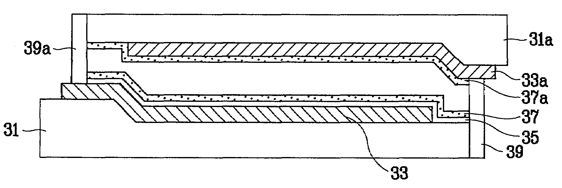
[0041]FIG. 3 is a plane view illustrating a flat luminescent lamp according to the present invention, FIG. 4 is a sectional view taken along line I–I′ of FIG. 3, and FIG. 5 is a sectional view taken along line II–II′ of FIG. 3.

[0042]As shown in FIGS. 3 to 5, the flat luminescent lamp according to the present invention includes first and second substrates 31 and 31a attached to each other to face each other, each having a plurality of grooves on an attached surface. First and second electrodes 33 and 33a are arranged in the grooves to be separated from each other in the up and down direction. First and second phosphor layers 37 and 37a are formed in the grooves including the first and second electrodes 33 and 33a. First and second frames 39 and 39a are used for sealing the first and second substrates 31 and 31a.

[0043]The fir...


PUM


Abstract

A flat luminescent lamp includes first and second substrates attached to each other at a plurality of adhesive portions, a plurality of discharge spaces in regions other than the plurality of adhesive portions between the first and second substrates, first and second electrodes arranged in the discharge spaces to be separated from each other, first and second phosphor layers formed in the discharge spaces, and first and second frames sealing the first and second substrates.

Description

[0001]The present invention claims the benefit of Korean Patent Application No. P 2000-83097 filed in Korea on Dec. 27, 2000, which is hereby incorporated by reference.BACKGROUND OF THE INVENTION[0002]1. Field of the Invention[0003]The present invention relates to a luminescent lamp, and more particularly, to a flat luminescent lamp and a method for manufacturing the same.[0004]2. Discussion of the Related Art[0005]Ultra thin flat panel display devices, especially liquid crystal display (LCD) devices, are widely used in monitors for notebook computers, spacecrafts, and aircrafts.[0006]A passive luminescence LCD device usually includes a back light provided at the rear of a liquid crystal panel and used as a light source. The back light is inefficient because it increases the weight, power consumption, and thickness of the device.[0007]The back light used as a light source of an LCD is formed in such a manner that a cylindrical fluorescent lamp is often used. There are two types of b...

Claims


Application Information

Patent Timeline
Patent Type & Authority Patents(United States)
IPC IPC(8): H01J63/02H01J61/00H01J63/04H01J61/78H01J9/02H01J61/30
CPCH01J61/305H01J9/02H01J61/78
Inventor PARK, HONG BAE
Owner LG DISPLAY CO LTD
Why Eureka
Try Eureka