
Rechargeable battery module and method for manufacturing the same

a rechargeable battery and module technology, applied in the field of rechargeable battery modules, can solve the problems of limited amount of lithium in the earth, high energy consumption, and general extraction of lithium, and achieve the effects of reducing the related costs and environmental problems, widening the application field, and reducing manufacturing costs

Active Publication Date: 2019-03-21
UNIST ULSAN NAT INST OF SCI & TECH
View PDF4 Cites 3 Cited by
  • Summary
  • Abstract
  • Description
  • Claims
  • Application Information

AI Technical Summary

Benefits of technology

This patent describes a new type of battery that uses a special electrolyte and environmentally-friendly and safe solutions. By connecting multiple batteries in a specific way, a high-capacity battery module can be created. This design reduces manufacturing costs and assembly problems, and also allows for a larger size and easier maintenance. Overall, this patent presents a technical solution for creating efficient, safe, and cost-effective batteries.

Problems solved by technology

However, only a limited amount of lithium exists in the earth, and the lithium is generally obtained through difficult processes from minerals, salts, and the like.
Since high cost and high energy are required for manufacturing the lithium rechargeable battery, a next generation rechargeable battery that may replace the lithium rechargeable battery is needed.
The lithium rechargeable battery may explode, and since a lithium metal oxide (e.g., LiCoO2, LiMn2O4, etc.) used as a positive electrode active material is expensive, high cost is required for realizing a large storage system (an energy storage system (ESS)), and when a wasted lithium rechargeable battery is processed, environmental problems may occur.
In addition, since facilities associated with lithium rechargeable batteries are mistaken for facilities such as nuclear power plants, when sites for them are selected, social issues such as opposition of residents may occur.
To solve these problems, it is essential to reduce the risk of explosion, to select a material that is environmentally friendly, is abundant in the earth, and is inexpensive, and to develop a battery system that may preemptively prevent conflicts with community members when a site therefor is selected, but study results for them are insufficient.

Method used


Image

  • Rechargeable battery module and method for manufacturing the same
  • Rechargeable battery module and method for manufacturing the same
  • Rechargeable battery module and method for manufacturing the same

Examples


first exemplary embodiment

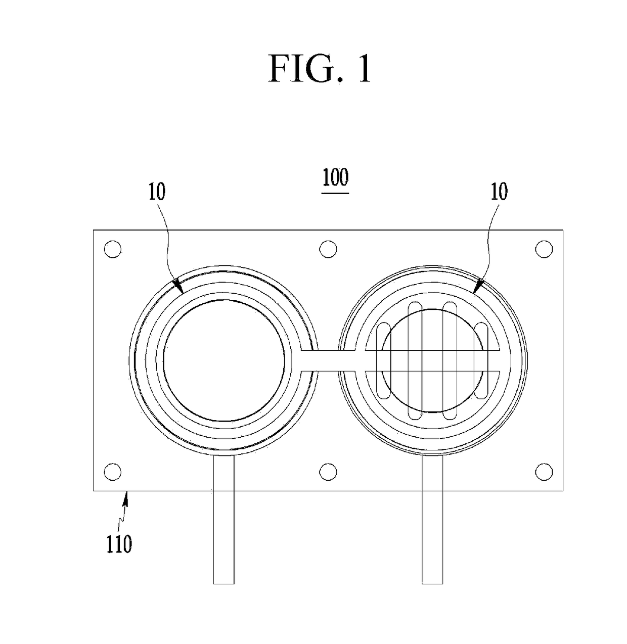
[0069]FIG. 1 illustrates a rechargeable battery module according to a first exemplary embodiment of the present invention.

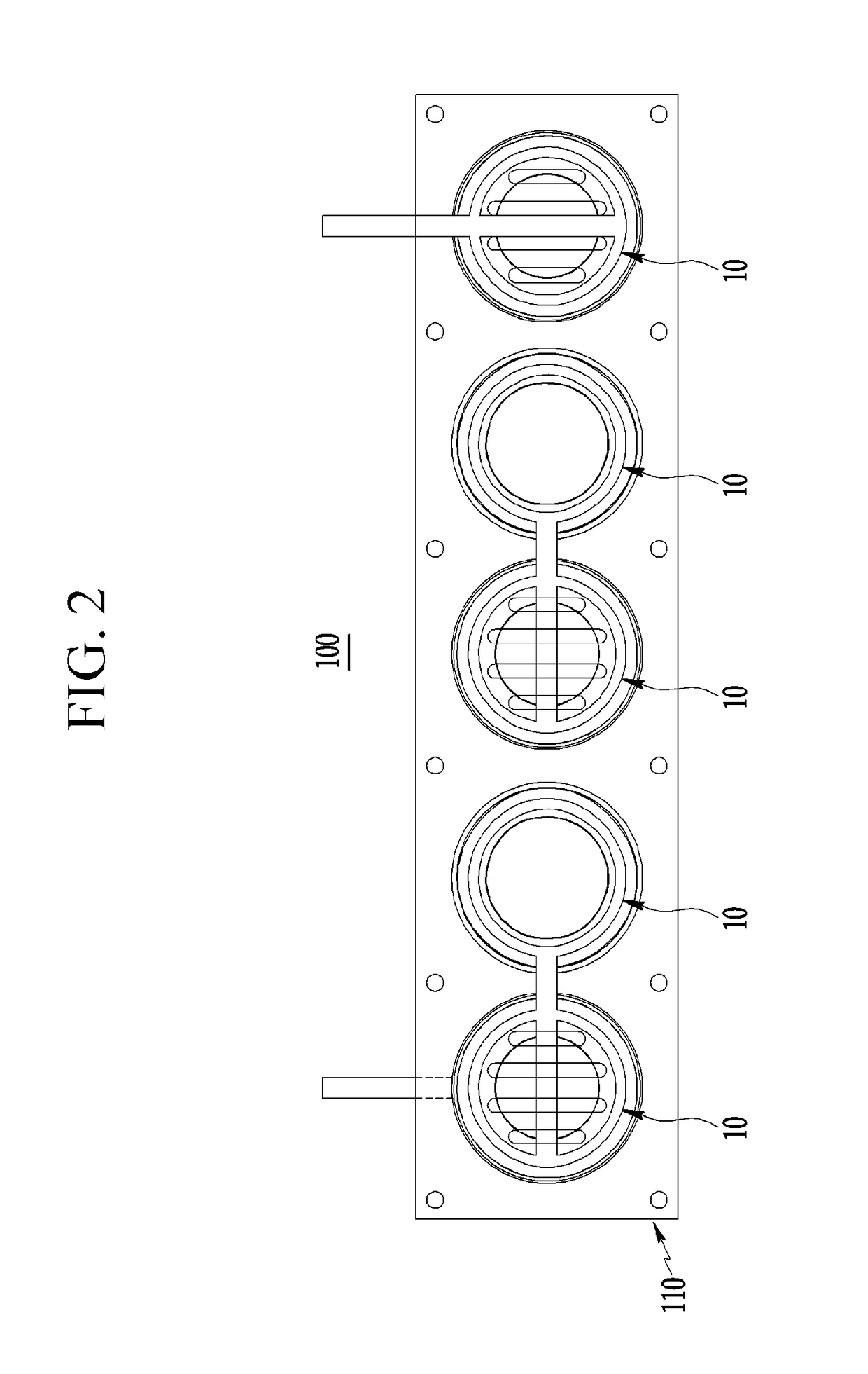
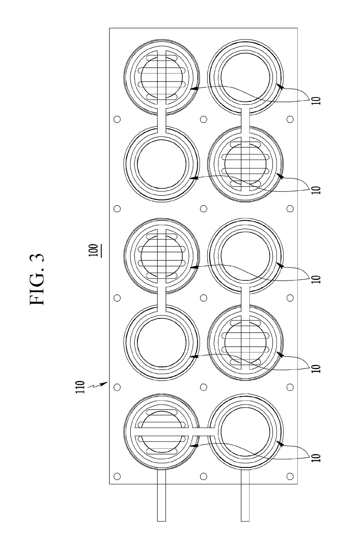
[0070]FIG. 1 to FIG. 3 respectively illustrate a rechargeable battery module 100 in which a plurality of coin batteries 10 are connected in series, and specifically, FIG. 1 illustrates a structure in which two coin batteries 10 are connected in series, FIG. 2 illustrates a structure in which five coin batteries 10 are connected in series, and FIG. 3 illustrates a structure in which ten coin batteries 10 are connected in series.

[0071]Since the rechargeable battery modules 100 in illustrated in FIG. 1 to FIG. 3 have the same configuration except for the number of coin batteries 10 and the number of parts according the number of coin batteries 10, the first exemplary embodiment will be described with reference to the rechargeable battery module 100 of FIG. 1 in which the two coin batteries 10 are connected in series.

[0072]FIG. 4 illustrates a configuration of the re...

second exemplary embodiment

[0137]FIG. 6 and FIG. 7 respectively illustrate a rechargeable battery module according to a second exemplary embodiment of the present invention, that is, a large-capacity rechargeable battery module in which a plurality of coin batteries are connected in parallel.

[0138]A structure of a rechargeable battery module 200 of the present exemplary embodiment is the same as that of the rechargeable battery module of the first exemplary embodiment described above except that the plurality of coin batteries 10 are connected in parallel. Thus, like reference numerals designate like or similar constituent elements, and a detailed description thereof will be omitted.

[0139]In the rechargeable battery module having a parallel connection structure, the number of the coin batteries 10 may be variously changed.

[0140]The rechargeable battery module 200 of the present exemplary embodiment includes the plurality of coin batteries 10 and the battery pack 110 that supports the plurality of coin batteri...

third exemplary embodiment

[0150]FIG. 8 and FIG. 9 respectively illustrate a rechargeable battery module according to a third exemplary embodiment of the present invention.

[0151]As shown in FIG. 8 and FIG. 9, a rechargeable battery module 300 of the present exemplary embodiment includes a plurality of unit cells 11 and the battery pack 110 that supports the plurality of unit cells 11 and electrically connects them.

[0152]Thus, the plurality of unit cells 11 are connected in parallel in one battery pack 110 to form a large-capacity rechargeable battery module 300.

[0153]As described above, the unit cell 11, as a minimum unit of a rechargeable battery, includes the negative electrode 13, the positive electrode 12, and the solid electrolyte 14 positioned between the negative electrode 13 and the positive electrode 12.

[0154]The unit cell 11 and the battery pack 110 are assembled to substantially form the rechargeable battery, and according to the present exemplary embodiment, the plurality of unit cells 11 are moun...


PUM

PropertyMeasurementUnit
lattice structureaaaaaaaaaa
circumferenceaaaaaaaaaa
outer diameteraaaaaaaaaa

Abstract

A exemplary embodiment of the present invention provide a coin-type rechargeable battery module and a method for manufacturing the same in which a solid electrolyte selectively passing specific metal ions is applied to a negative electrode, an ion-containing solution (e.g., seawater) including sodium, lithium, magnesium, and a combination thereof is applied to a positive electrode, and the ion-containing solution flows in from the outside of the positive electrode, and which may be modularized to realize a large-capacity battery.

Description

TECHNICAL FIELD[0001]The present invention relates to a rechargeable battery module and a method for manufacturing the same.BACKGROUND ART[0002]Generally, a rechargeable battery, a positive electrode and a negative electrode of which are made of materials that can electrochemically react, is a battery that may be charged or discharged through conversion between chemical energy and electrical energy. The rechargeable battery is mainly utilized in a vehicle, a ship, or the like that are required to store large amounts of electrical power.[0003]As a representative example of the rechargeable batteries, there is a lithium rechargeable battery that generates electrical energy by chemical potential change when metal (e.g., lithium, sodium, or the like) ions are intercalated and deintercalated in a positive electrode and a negative electrode.[0004]The lithium rechargeable battery is manufactured by utilizing materials that can reversibly intercalate and deintercalate the lithium ions as ac...

Claims


Application Information

Patent Timeline
Patent Type & Authority Applications(United States)
IPC IPC(8): H01M10/0562H01M2/10H01M4/66H01M2/08H01M2/20H01M10/38H01M50/147H01M50/186H01M50/209H01M50/216H01M50/227H01M50/296H01M50/503H01M50/51H01M50/512H01M50/522H01M50/528H01M50/543
CPCH01M10/0562H01M2/1038H01M4/663H01M2/08H01M2/204H01M2/0404H01M10/052H01M4/66H01M4/58H01M4/70H01M10/0585Y02E60/10H01M50/109H01M50/216Y02P70/50H01M50/522H01M50/186H01M50/512H01M50/51H01M50/147H01M50/503H01M50/209H01M50/543H01M50/296H01M50/227H01M50/20
Inventor KIM, YOUNG SIKGO, WOOSEOKHAN, JIN HYUP
Owner UNIST ULSAN NAT INST OF SCI & TECH
Learn More