Hip prosthesis and the use thereof

a technology for hips and prostheses, applied in the field of hip prostheses, can solve the problems of further deterioration of the prosthesis, and achieve the effects of reducing the motion of the ball and socket joint, and reducing the wear of the prosthesis parts

Inactive Publication Date: 2007-02-20
GREENLEE WILFRED E
View PDF28 Cites 63 Cited by
  • Summary
  • Abstract
  • Description
  • Claims
  • Application Information

AI Technical Summary

Benefits of technology

[0009]One object of the invention disclosed here is to lessen the motion of the ball and socket joint required during common activities, thereby reducing the wear of the prosthesis parts. However, it is important that that object be accomplished while allowing the full range of motion afforded by a ball and socket joint. Reducing wear is particularly important given the biological effects of wear debris. The wear debris of a conventional hip prosthesis is known to trigger inflammatory responses, which, among other things, can contribute to further deterioration of the prosthesis.
[0010]The invention disclosed here is a femur side hip prosthesis having a secondary bearing system in addition to the primary bearing system. That secondary bearing system facilitates motion of the femur that is, generally speaking, involved in swinging the leg frontward and rearward. It is designed to be used in conjunction with a pelvis-side prosthesis similar to those conventionally used. This arrangement allows motion by way of the primary bearing system (in the conventional ball and socket manner) and, additionally, the freedom to rotate by way of the secondary bearing system. The degree of freedom afforded by this secondary bearing system allows the primary bearing system to undergo far less motion during certain common activities such as walking in a straight line. However, for leg actions requiring motions not fully accommodated by the rotation about the secondary bearing system, the primary bearing system can supply the needed freedom.

Problems solved by technology

The wear debris of a conventional hip prosthesis is known to trigger inflammatory responses, which, among other things, can contribute to further deterioration of the prosthesis.

Method used


Image

  • Hip prosthesis and the use thereof
  • Hip prosthesis and the use thereof
  • Hip prosthesis and the use thereof

Examples


embodiment i

[0017 and Embodiment II of the invention disclosed here are described below. They are similar to each other. The principle difference is that in Embodiment II of the invention disclosed here there is a modular connection between the stem for placement within the femur and the assembly that includes the secondary bearing.

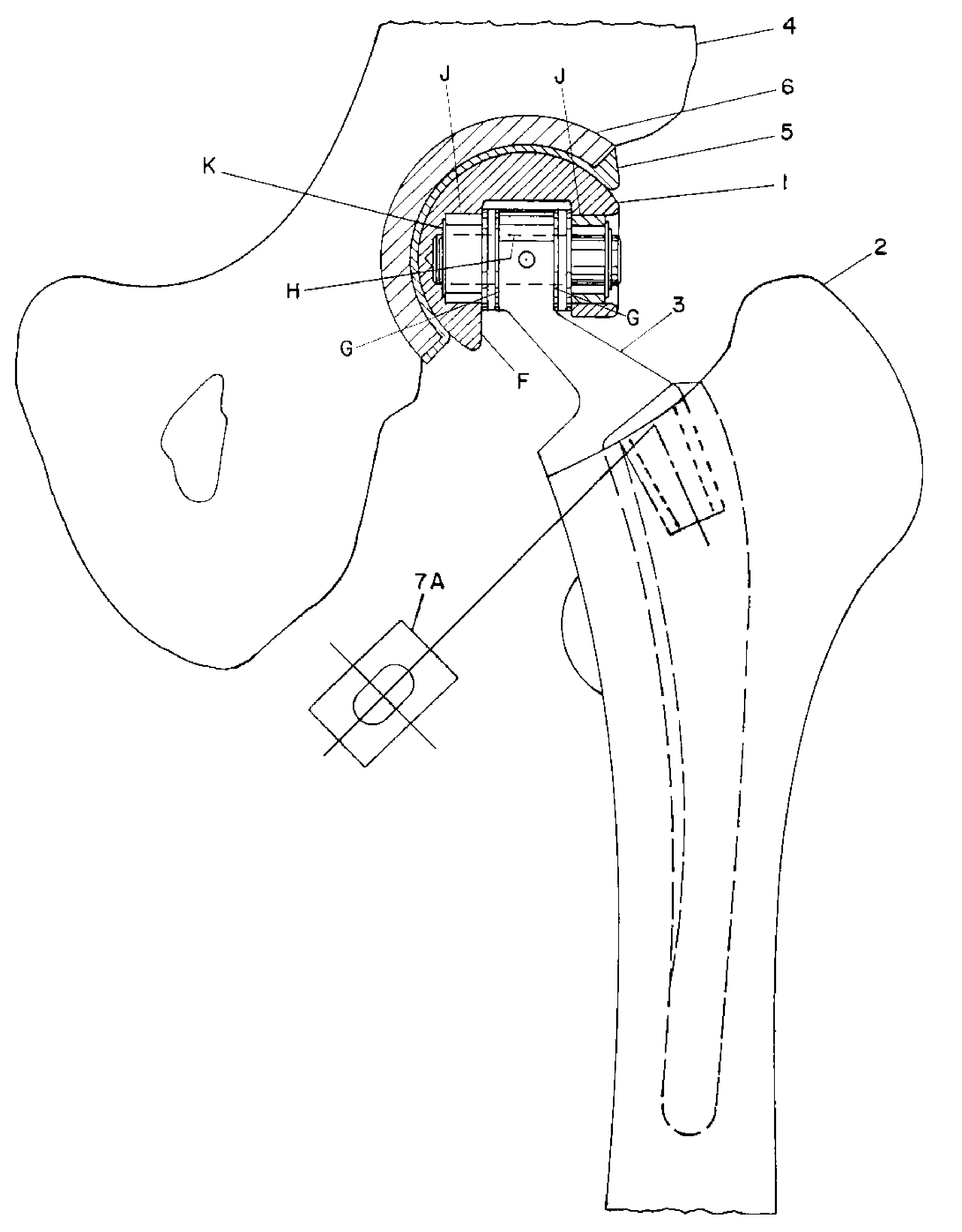
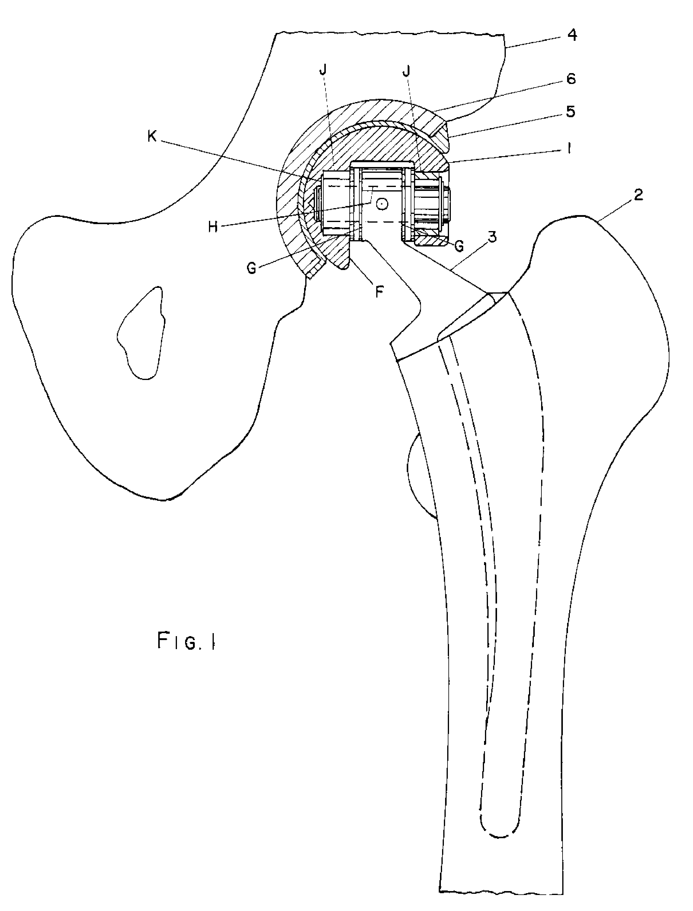
[0018]FIG. 1 is a partially cross-sectional depiction of Embodiment I of the invention disclosed here. More particularly, the pelvis, the primary bearing system and the secondary bearing system are shown in cross-section. The view is an anterior view of the left hip. FIG. 1 will be used in describing the general features of Embodiment I of the invention disclosed here. In Embodiment I, the ball 1 interfaces with a socket liner 5 within an acetabulum shell prosthetic implant 6 which is secured within the pelvis 4.

[0019]FIG. 4 is a partially cross-sectional depiction of Embodiment II of the invention disclosed here. More particularly, the pelvis, the primary bearing sy...


PUM


Abstract

Hip prosthesis. The femur side hip prosthesis includes both a ball and socket bearing and another (secondary) bearing system which facilitates motion of the type which is primarily in the forward and backward swinging of the leg. In certain embodiments of the invention, the secondary bearing system includes needle bearings and thrust bearings. That secondary bearing system lessens the motion of the ball and socket joint required during common activities such as walking. Certain embodiments of the invention include a modular connection between the stem for placement within the femur and the assembly that includes the secondary bearing.

Description

CLARIFICATIONS ABOUT SELECTED TERMS[0001]The term “prosthetic implant” is commonly used to refer not only to the item once implanted, but also to the item intended for implantation. That comprehensive meaning is embraced here.[0002]In prostheses with ball and socket joints, the ball and socket system is referred to here as the “primary bearing system.” In prostheses with both a ball and socket joint and another bearing system, the bearing system which is not the ball and socket system is referred to here as the “secondary bearing system.” These terms are for convenience of reference, and do not imply relative degrees of importance, stress or motion.BACKGROUND OF THE INVENTION[0003]Hip joint deterioration frequently leads to patients undergoing total hip replacement (total hip arthroplasty). Such hip joint deterioration has many causes including, but not limited to, degenerative arthritis, rheumatoid arthritis, ankylosing spondylitis, avascular necrosis (both primary and secondary), ...

Claims


Application Information

Patent Timeline
Patent Type & Authority Patents(United States)
IPC IPC(8): A61F2/32
CPCA61F2/32A61F2/36A61F2002/30495A61F2002/30514A61F2002/30639A61F2220/0025A61F2002/3233A61F2002/3448A61F2002/3493A61F2002/3611A61F2002/30645
Inventor GREENLEE, WILFRED E.
Owner GREENLEE WILFRED E
Why Eureka
Try Eureka