Screw scissor lift

a scissor lift and screw technology, applied in the field of scissor lifts, can solve the problems of screw mechanism bind, significant mechanical disadvantage, screw mechanism bind, etc., and achieve the effect of reducing the side to side sway of the scissor mechanism and therefore of the payload

Inactive Publication Date: 2006-08-17
HANLON ENG
View PDF13 Cites 61 Cited by
  • Summary
  • Abstract
  • Description
  • Claims
  • Application Information

AI Technical Summary

Benefits of technology

[0007] At a fully retracted position, the scissored arms define a support angle of at least 150°, more preferably at least 165°, still more preferably at least 175°, and most preferably 180°. At the extreme of 180°, this corresponds to an angle of 0° between the screw drive and the lowest arm of the scissors, which means that such scissor lifts can be considerably more compact than prior art lifts.
[0008] In another aspect of preferred embodiments, a bearing is used at a pivot joining the first and second arms, with hardened washers on either sides of the bearing. These features help reduce side to side sway of the scissor mechanism, and therefore of the payload. In especially preferred embodiments the bearing is sufficiently stiff to restrict side to side movement of the payload such that movement of the payload under operation of the lift is substantially planar.

Problems solved by technology

Despite these varied uses, and the considerable experience of decades of use, there are still problems associated with screw-type scissor lifts.
One problem is that the screw mechanism tends to bind.
Another problem is that there is a very significant mechanical disadvantage-working against extension of the scissor mechanism in a compressed position.

Method used


Image

  • Screw scissor lift
  • Screw scissor lift
  • Screw scissor lift

Examples


Embodiment Construction

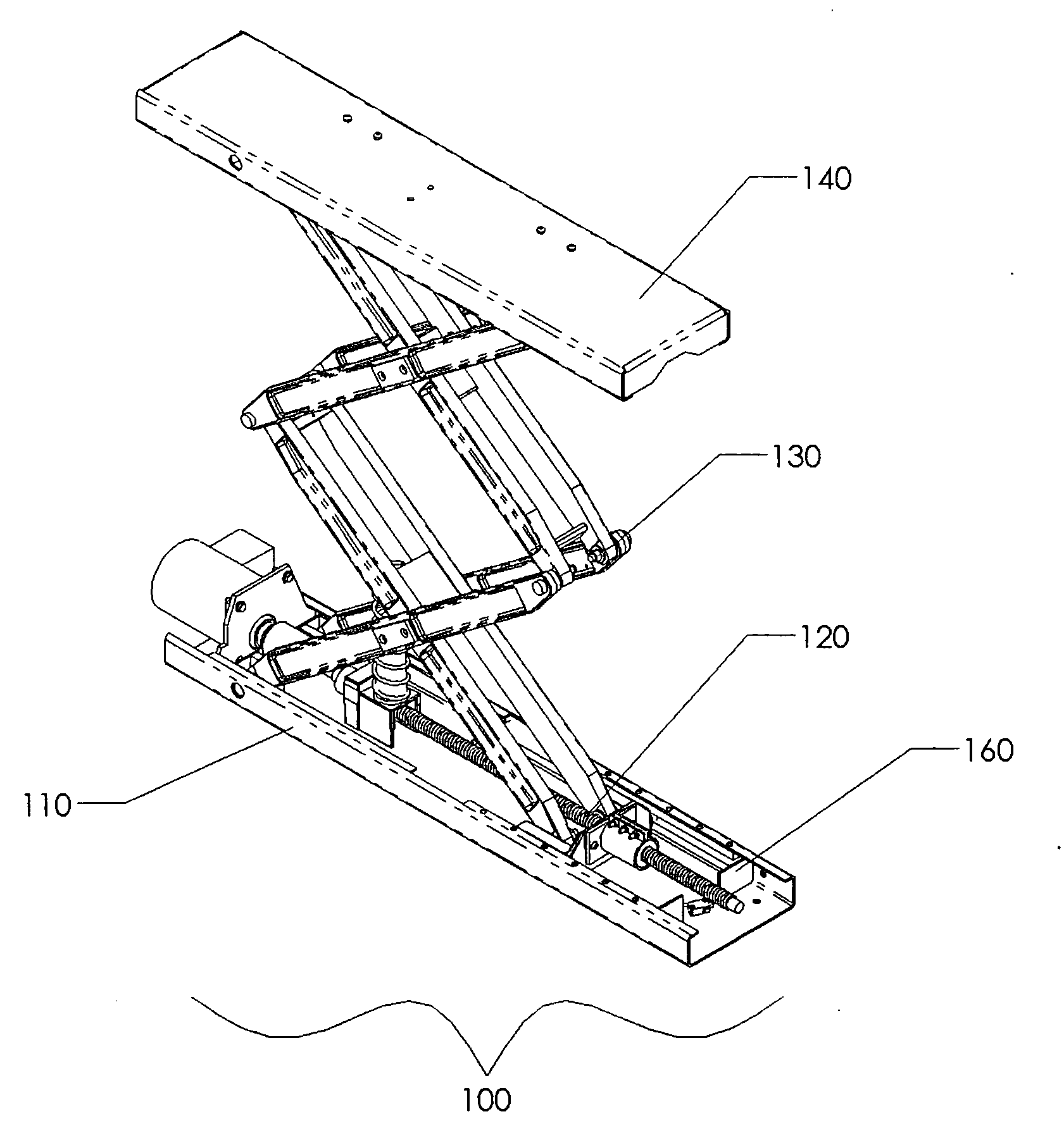
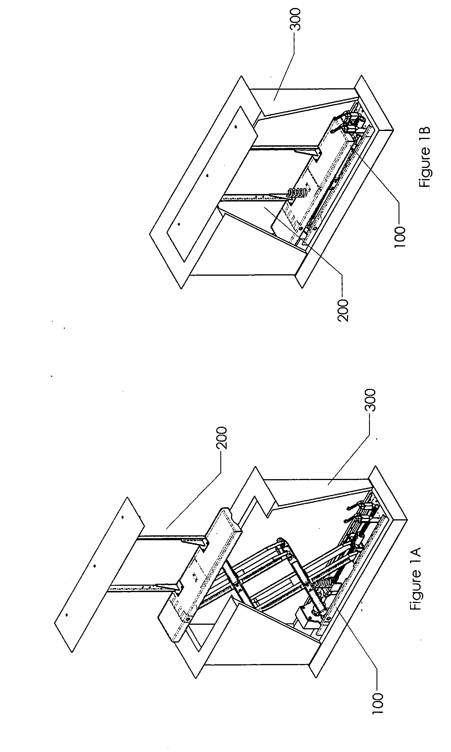
[0023]FIGS. 1A and 1B generally depict a lift 100 supporting a plasma screen 200 and a cabinet 300. In FIG. 1A the screen is fully extended to a viewing position outside the cabinet 300, and in FIG. 1B the fully retracted screen is descended into the main cavity of cabinet 300. The lift 100 generally includes a base assembly 110, counter balance spring 111, a thrust bearing frame 112, a thrust bearing 113, a thrust bearing race 114, a shaft bearing 115, a drive screw 116, a drive nut assembly 117, and a base frame 118.

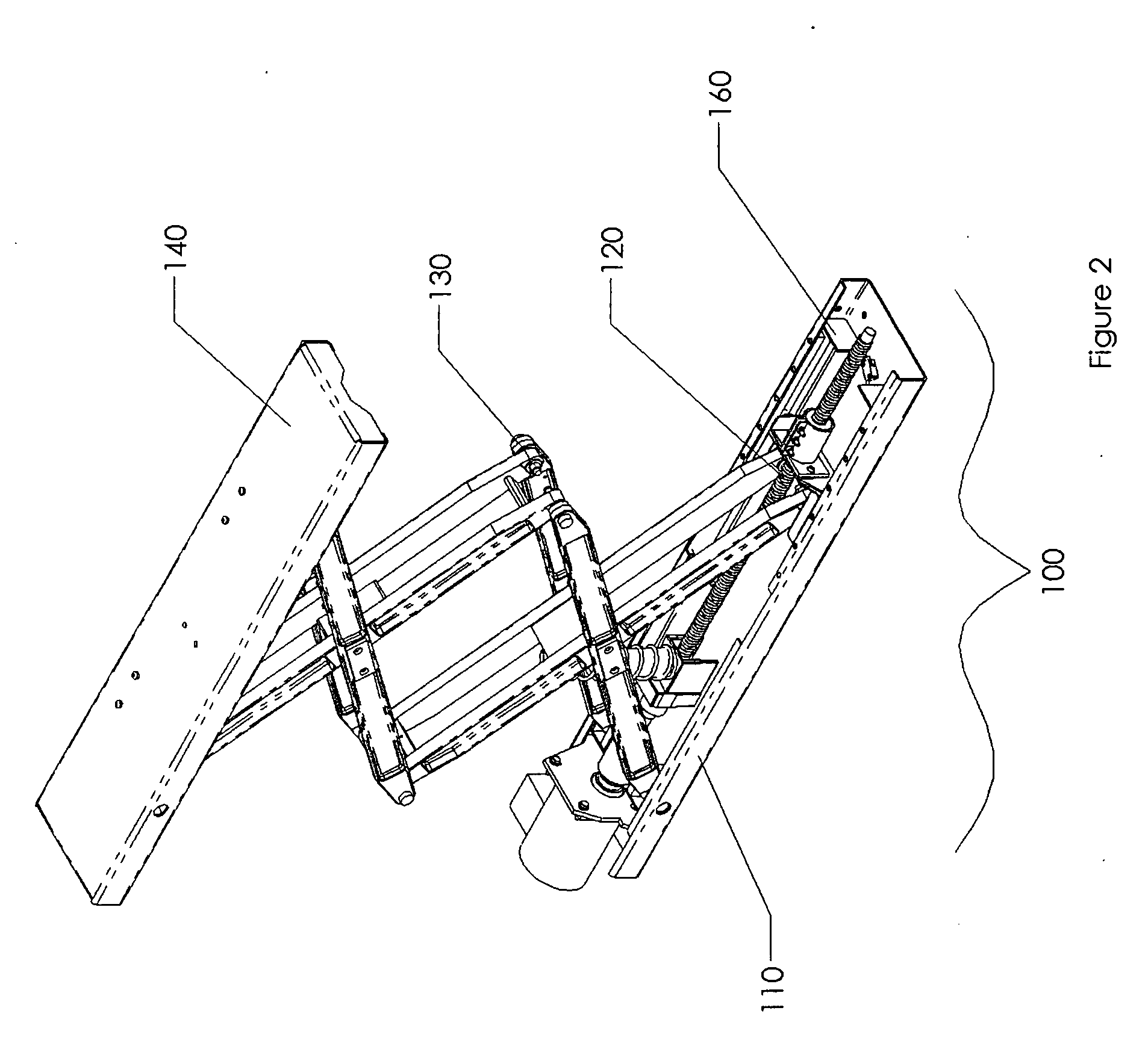
[0024] In FIG. 2 the lift 100 is shown supporting a superstructure comprising a platform assembly 140, which is coupled to a cap frame 150. Details of the superstructure are better visualized in FIGS. 6 and 7, which show the upper platform assembly 140 as including a upper platform frame 141 and screen brackets 142A, 142B. The cap frame 150 generally includes a cap 151, a machine screw 152, springs 153, washers 154, and nuts 155. The springs 153 permit self-leveling o...


PUM


Abstract

A scissor lift includes an energy storage device that stores energy as the payload is lowered, and provides further lift to the payload as the payload is raised. This allows the scissors to achieve a support angle of up to 180° between the two arms (down to 0° between the screw drive and the lowest arm of the scissors), making the inventive scissor lifts considerably more compact than prior art lifts. The energy storage device is preferably a helical wire spring, but can alternatively be any suitable spring, piston, or even an elastomeric mass. Side to side movement of the scissors arms can be restricted using a thrust bearing with hardened washers at the inter-arm pivot, and / or a guided connector that transmits motive force to the scissors.

Description

[0001] This application claims priority to U.S. provisional application Ser. No. 60 / 642,267 filed Jan. 7, 2005.FIELD OF THE INVENTION [0002] The field of the invention is scissor lifts. BACKGROUND OF THE INVENTION [0003] Scissor lifts have been widely used across many applications for many years. Among other things, such lifts have been used to raise automobiles and other heavy equipment, people, building components, supplies, structural components, and to provide scaffolding, work stands, patient beds and so forth. Operation of the scissor must be operated in some manner, and in some instances the scissor is operated using a screw drive. Examples in the patent literature include U.S. Pat. No. 6,719,282 to Frank (April 2004); U.S. Pat. No. 6,684,443 to Thomas et al. (February 2004); US20040005961 to lund et al. (January 2004); U.S. Pat. No. 6,655,875 to Pignato (December 2003); U.S. Pat. No. 5,996,961 to Johnson (December 1999); and U.S. Pat. No. 5,593,137 to Johnson (January 1997);...

Claims


Application Information

Patent Timeline
Patent Type & Authority Applications(United States)
IPC IPC(8): B66B9/02
CPCB66B9/0815B66F7/0608B66F7/0633B66F7/0666B66F7/28Y02B50/144Y02B50/00
Inventor HANLON, MARK T.
Owner HANLON ENG
Why Eureka
Try Eureka