Abrasion resistant pump thrust bearing

a technology of thrust bearings and pumps, which is applied in the direction of machines/engines, stators, liquid fuel engines, etc., can solve the problems of wear and tear of pump components, and the impulsion may exert upward thrust, and achieve the effect of a large surface area

Active Publication Date: 2009-08-18
BAKER HUGHES INC
View PDF20 Cites 60 Cited by
  • Summary
  • Abstract
  • Description
  • Claims
  • Application Information

AI Technical Summary

Problems solved by technology

Also, particularly at startup and when the fluid flow is nonuniform, the impellers may exert upward thrust.
The abrasive material causes wear of the pump components, particularly in the areas where downward thrust and upward thrust are transferred.

Method used


Image

  • Abrasion resistant pump thrust bearing
  • Abrasion resistant pump thrust bearing
  • Abrasion resistant pump thrust bearing

Examples


Embodiment Construction

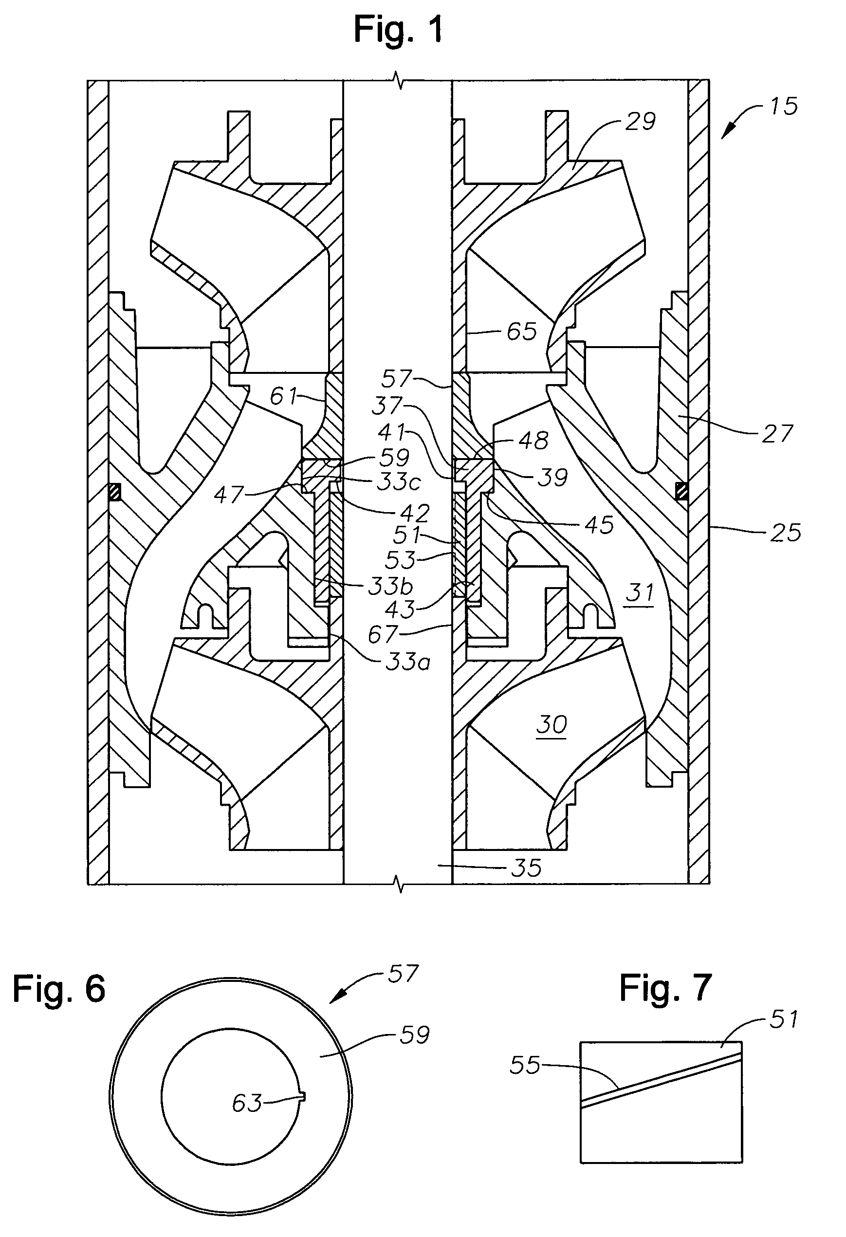
[0014]Referring to FIG. 2, a pump assembly is shown in a well having a casing 11. Perforations 13 within casing 11 allow well fluid to flow into the casing 11. An electrical submersible pump 15 is shown suspended in the well on a string of production tubing 17. Pump 15 has an intake 19 for drawing in well fluid and pumping it through tubing 17 to the surface. Alternately, in some instances pump 15 will discharge into casing 11 above a packer (not shown).

[0015]Pump 15 has a seal section 21 connected to its lower end. An electrical motor 23 connects to the lower end of seal section 21. Seal section 21 reduces a pressure differential between lubricant within motor 23 and the hydrostatic pressure in the well. An electrical power cable 24 extends downward from the surface to motor 23 for supplying power.

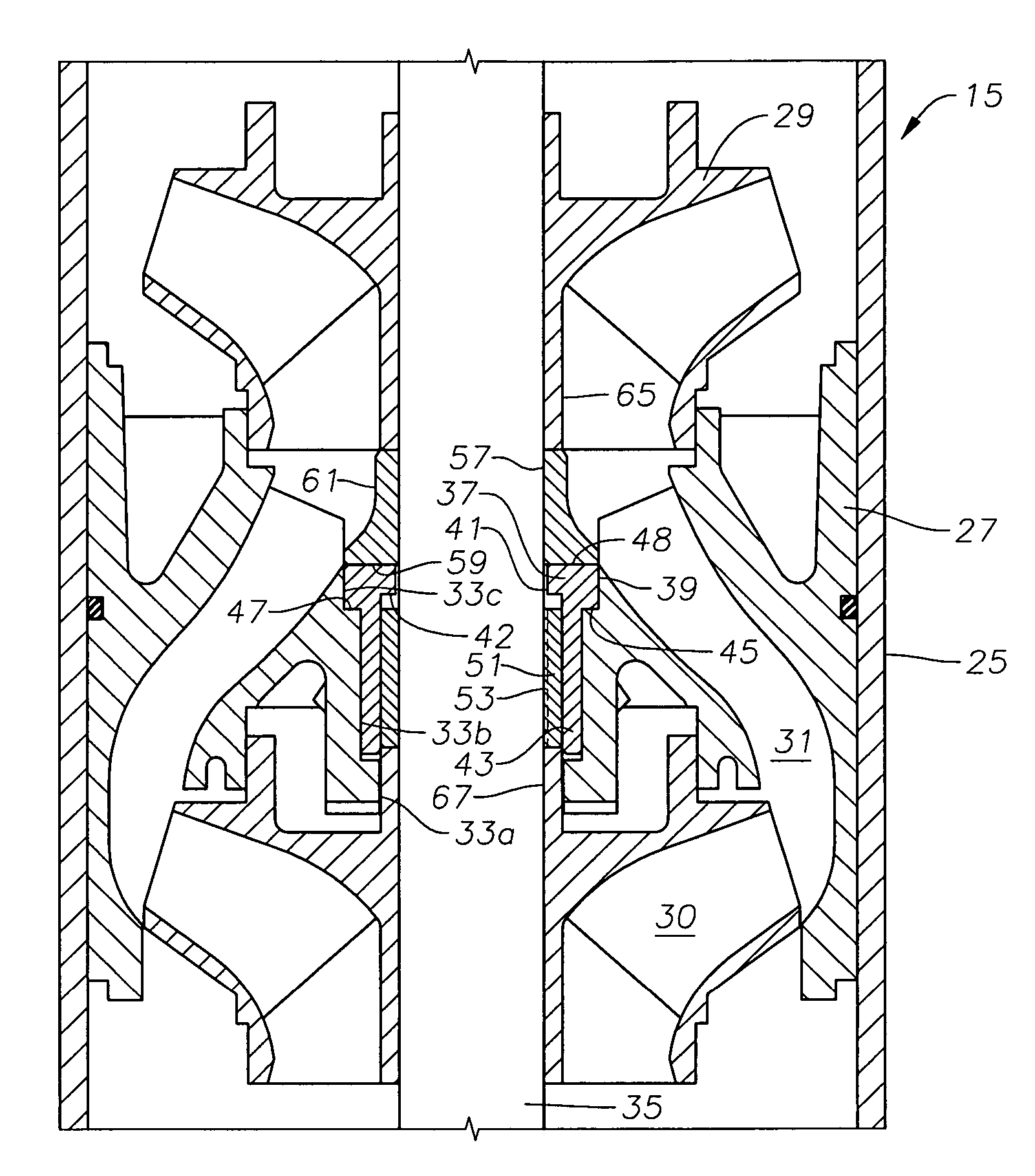
[0016]Referring to FIG. 1, pump 15 is a centrifugal pump made up of a plurality of stages. Each stage has a diffuser 27 (one shown) and an impeller 29 (two shown). Each impeller rotates a...


PUM


Abstract

A centrifugal pump has a stationary diffuser with a bore. A thrust bearing has a tubular portion that inserts into the bore. The thrust bearing has an external shoulder that contacts a support surface in the bore of the diffuser for transmitting downward thrust from an upstream impeller to the diffuser. The thrust bearing has an internal shoulder for transmitting upward thrust from a downstream impeller to the diffuser.

Description

CROSS REFERENCE TO RELATED APPLICATION[0001]This application claims priority to provisional application 60 / 660,737, filed Mar. 11, 2005.FIELD OF THE INVENTION[0002]This invention relates in general to electrical submersible well pumps and in particular to thrust bearings for a centrifugal pump.BACKGROUND OF THE INVENTION[0003]Centrifugal well pumps are commonly used for pumping oil and water from oil wells. The pumps have a large number of stages, each stage having a stationary diffuser and a rotating impeller. The rotating impellers exert a downward thrust as the fluid moves upward. Also, particularly at startup and when the fluid flow is nonuniform, the impellers may exert upward thrust. In the most common pump design, the impellers float freely on the shaft so that each impeller transfers downward thrust to one of the diffusers. A thrust washer or bearing is located between a portion of each impeller and the upstream diffuser to accommodate the downward thrust. Another thrust was...

Claims


Application Information

Patent Timeline
Patent Type & Authority Patents(United States)
IPC IPC(8): F01D3/00F01D25/16F04D29/04
CPCF04D1/063F04D29/047F04D29/0413F04D1/06F04D29/046F04D29/448
Inventor SEMPLE, RYAN P.DELONG, ROBERT C.BRUNNER, CHRISTOPHERPORETTI, ARTURO L.SHAFER, TERRY W.
Owner BAKER HUGHES INC
Why Eureka
Try Eureka