Low profile fluid dynamic bearing

a dynamic bearing and low-profile technology, applied in sliding contact bearings, record information storage, instruments, etc., can solve the problems of physical contact, vibration generation, and prone to the above-mentioned bearing system, and achieve simple and scalable design, maintain dynamic performance, and reduce the amount of power consumed during rotation

Inactive Publication Date: 2006-01-03
SEAGATE TECH LLC
View PDF32 Cites 60 Cited by
  • Summary
  • Abstract
  • Description
  • Claims
  • Application Information

AI Technical Summary

Benefits of technology

[0016]It is an objective of the invention to provide a hydrodynamic bearing which is simple and scalable in design, which diminishes the amount of power consumed during rotation while maintaining dynamic performance under operating vibration conditions.

Problems solved by technology

The conventional bearing system described above is prone, however, to several shortcomings.
First, vibration is generated by the balls rolling on the raceways.
Ball bearings used in hard disk drive spindles run under conditions that often cause physical contact between raceways and balls in spite of the lubrication layer provided by the bearing oil or grease.
This vibration results in misalignment between the data tracks and the read / write transducer.
These imperfections reduce the lifetime and effectiveness of the disc drive system.
Another problem is related to the use of hard disk drives in portable computer equipment and the resulting requirements for shock resistance.
Since the contact surface in ball bearings is very small, the resulting contact pressures may exceed the yield strength of the bearing material and leave permanent deformation and damage on raceways and balls.
Moreover, mechanical bearings are not always scaleable to smaller dimensions.
This is a significant drawback since the tendency in the disc drive industry has been to continually shrink the physical dimensions of the disc drive unit, as well as operate the units at ever-increasing speeds.
Another problem is that of potential leakage of grease or oil into the atmosphere of the disc drive, or outgassing of the components into this atmosphere.
Because of the extremely high tolerance required for smaller radial spacing between tracks on the disc and the gap in the transducer which is used to read and write data on the disc, discs are located within sealed housings in which contaminants cannot be tolerated.
However, air cannot provide the lubricating qualities of oil or the load capacity.
The liquid lubricant must be sealed within the bearing to avoid a loss which would result in reduced bearing load capacity and life.
Otherwise, the physical surfaces of the spindle and of the housing would come into contact with one another leading to accelerated wear and eventual failure of the bearing system.
A shortcoming of known hydrodynamic bearings includes the fact that many prior art hydrodynamic bearing assemblies require large or bulky structural elements for supporting the axial and radial loads, as many hydrodynamic bearings do not have the inherent stiffness of mechanical bearing assemblies.
It is difficult to scale the structural support elements to fit within the smaller disc drive dimensions currently in demand.
In other instances, hydrodynamic bearing assemblies require extremely tight clearances and precise alignments.
This burden makes it difficult to manufacture such assemblies since even a small deviation or aberration can lead to faulty bearings.
Further, as the gaps in which the fluid is located become smaller, the power consumed to rotate the spinning elements.
The NRRO of a ball bearing motor is often too high for today's disc drives.
One problem with this conventional FDB spindle motor arrangement is that it limits the degree to which the height of the motor assembly may be reduced.
Moreover, use of a thrust bearing increases the amount of friction the motor must overcome during operation, increasing power consumption.
In the field of fluid dynamic bearing motors for use in hard disc drives, some prior systems including, but not limited to, small form factor motor designs for mobile applications have been limited by stringent power requirements.
This approach results in bear gaps at large diameters, thereby increasing bearing drag and overall motor power.

Method used


Image

  • Low profile fluid dynamic bearing
  • Low profile fluid dynamic bearing
  • Low profile fluid dynamic bearing

Examples


Embodiment Construction

[0041]The following description of a preferred embodiment of the invention is given with reference to its use in a disc drive, since disc drives are especially directed to incorporating motors of a low profile. However, the present invention may also be useful in many other formats and environments.

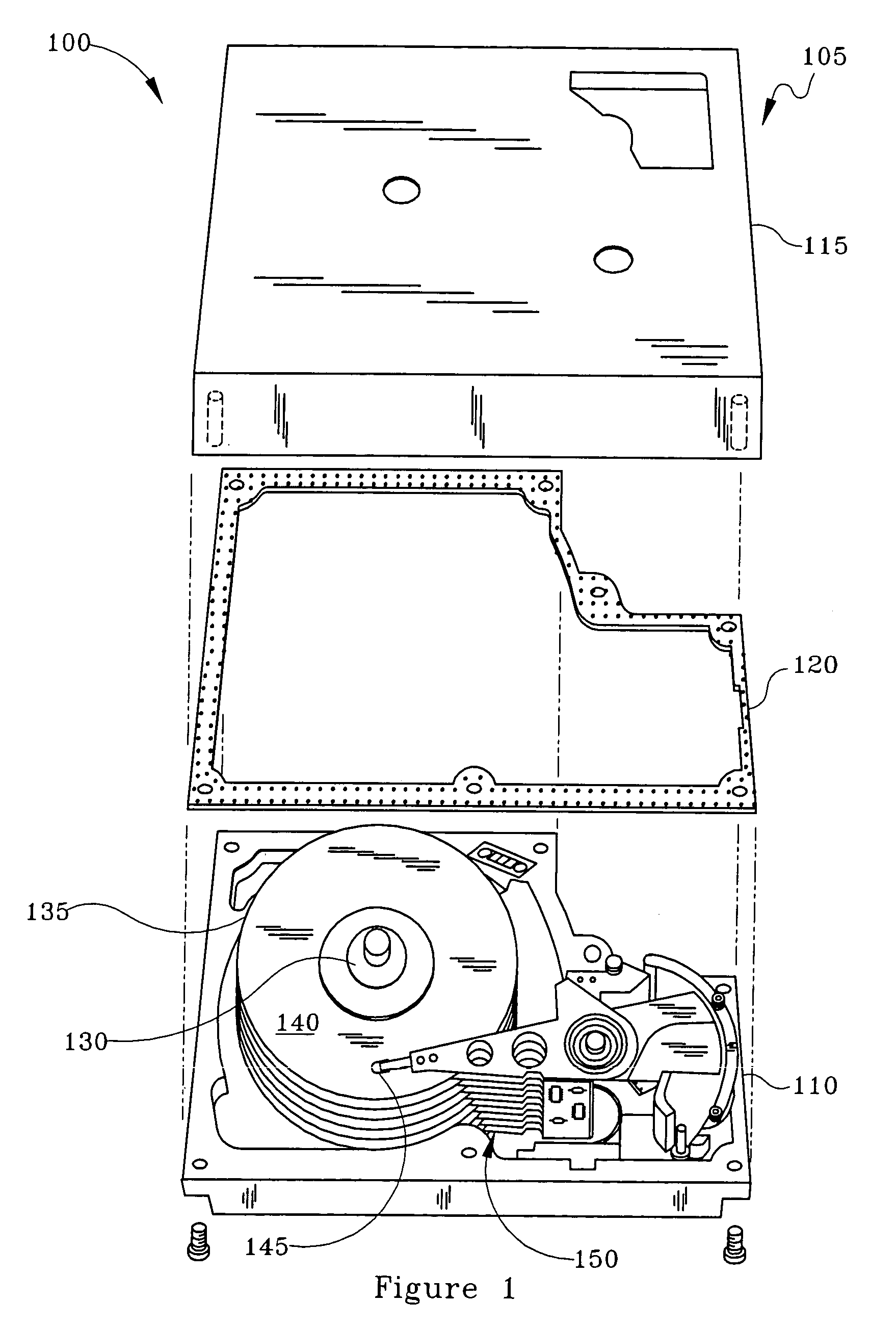
[0042]Thus, as an exemplary environment for use in the present invention, FIG. 1 shows an exploded perspective view of a disc drive storage system in which the present bearing and motor would be useful. FIG. 1 is provided primarily to give an illustrative example of the environment in which a motor incorporating the bearing comprising the features of the present invention is used; clearly, the motor could be used equally well in other designs of disc drives, or other operating environments apart from disc drive technology where minimizing the start and run power for the disc drive motor, and / or minimizing the overall height of the motor is a desirable feature.

[0043]More particularly, in F...


PUM

PropertyMeasurementUnit
temperatureaaaaaaaaaa
axial displacementaaaaaaaaaa
pressureaaaaaaaaaa

Abstract

The design comprises a shaft and sleeve supported for relative rotation by a journal type fluid dynamic bearing utilizing grooves on one of the shaft or sleeve surfaces. A grooved pattern of a design similar to that usually found on a thrust plate is defined on an axial end surface of the shaft or the counterplate facing the axial end of the shaft, so that thrust is created to maintain separation of the end of the shaft and the facing thrust plate during relative rotation.
In one embodiment, to establish and maintain the gap between the shaft end and the facing counterplate, the journal bearing has an asymmetry to pump toward the shaft end having the bearing. In a further refinement, to maintain the shaft and gap within an optimum spacing, a magnet is mounted to provide an axially directed magnetic force on the shaft which works against the axial force created by shaft end thrust bearing.
To prevent separation of the shaft and sleeve or hub, the hub which is integrated with a rotating shaft, further incorporates a shoulder which extends axially beneath a cooperating shoulder on the sleeve surrounding the shaft to prevent any more than a limited axially displacement of the hub and shaft relative to the sleeve.

Description

CROSS REFERENCE TO A RELATED APPLICATION[0001]This application claims priority to a Provisional Application Ser. No. 60 / 342,681, filed Dec. 20, 2001, in the names of Aiello, Kloeppel and Flores, which application is incorporated herein by reference.FIELD OF THE INVENTION[0002]This invention relates to fluid dynamic bearing motors, and more particularly to such motors without thrust plate.BACKGROUND OF THE INVENTION[0003]Disc drive memory systems have been used in computers for many years as storage space for digital information. Information is recorded on concentric memory tracks of magnetic discs that rotate around a spindle. Information is accessed by read / write heads located on a pivoting arm which moves radially over the surface of the disc. The read / write heads (-transducers-) must be accurately aligned with the storage tracks on the disc to ensure proper reading and writing of information.[0004]The discs are rotated at high speeds in an enclosed housing by means of an electric...

Claims


Application Information

Patent Timeline
Patent Type & Authority Patents(United States)
IPC IPC(8): H02K7/09H02K21/22F16C17/10F16C33/10G11B19/20
CPCF16C17/045F16C17/10F16C33/107G11B19/2009F16C25/045F16C2370/12F16C17/107
Inventor AJELLO, ANTHONY JOSEPHKLOEPPEL, KLAUS DIETERFLORES, GREGOR PACO
Owner SEAGATE TECH LLC
Why Eureka
Try Eureka