
Patient transfer system for use in stereotactic radiation therapy

a technology for stereotactic radiation therapy and patient transfer, which is applied in the direction of wheelchair/patient conveyance, application, transportation and packaging, etc., can solve the problems of considerable friction, considerable friction, and considerable friction

Active Publication Date: 2012-05-08
MEDTEC LLC
View PDF6 Cites 7 Cited by
  • Summary
  • Abstract
  • Description
  • Claims
  • Application Information

AI Technical Summary

Benefits of technology

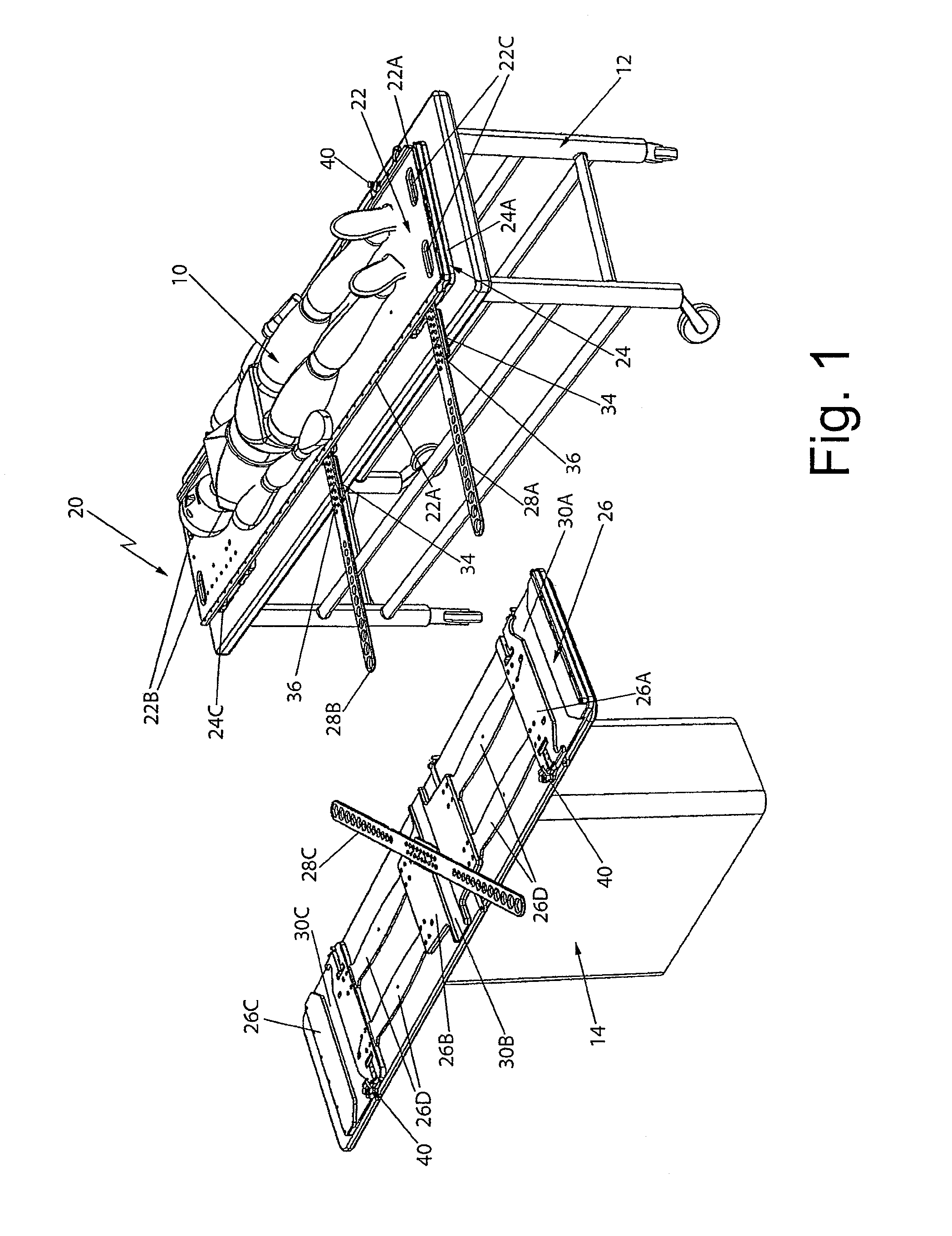
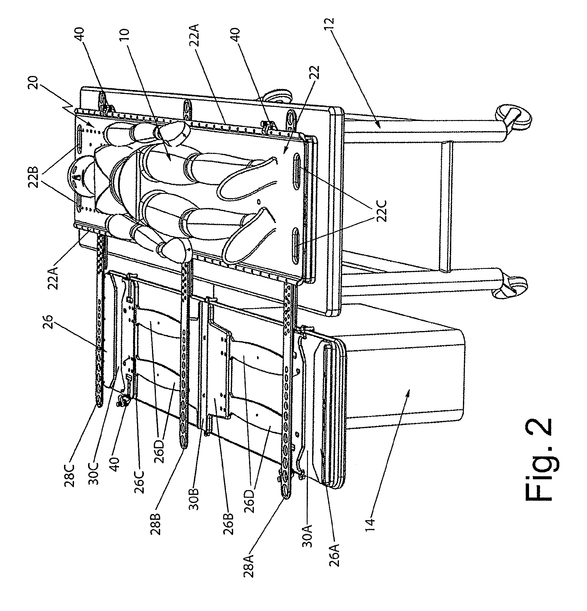
[0013]In accordance with another aspect of this invention the system additionally comprises at least one bridging member and wherein the first base member comprises at least one first recess therein and the second base member comprises at least one second recess therein. The at least one bridging member is arranged to be located within the at least one first and second recess to bridge any space between the first and second support structures so that the patient support panel can be readily slid from the first base member to the second base member and vice versa via the at least one bridging member.

Problems solved by technology

In particular, when the transfer board has been located in the position bridging the space between the gurney and the treatment couch it leaves a considerable portion of the sheet on the treatment couch exposed and a considerable portion of the sheet or covering of the gurney's pad exposed.
Thus, there is considerable friction when sliding the patient and his / her sheet onto the bridging board and then off of the bridging board and fully onto the treatment couch.
In a similar manner, there is considerable friction that has to be overcome when using the bridging board to transfer the patient back from the treatment couch to the gurney when the patient's treatment has been completed.
There are some roller systems which are designed to effect the transfer of the patient from the gurney to the treatment table and vice versa, but those systems are somewhat complex and still leave much to be desired.

Method used


Image

  • Patient transfer system for use in stereotactic radiation therapy
  • Patient transfer system for use in stereotactic radiation therapy
  • Patient transfer system for use in stereotactic radiation therapy

Examples


Embodiment Construction

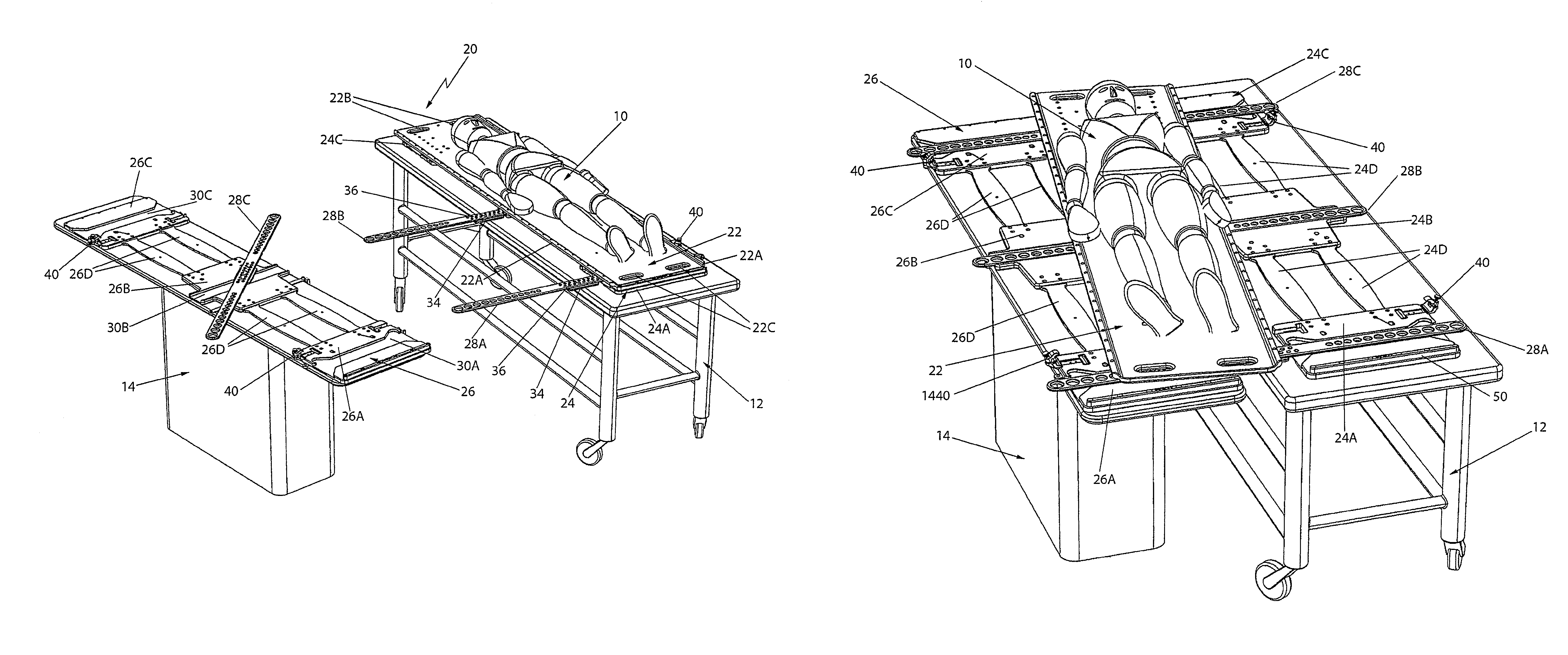
[0029]Referring now to the various figures of the drawing wherein like reference characters refer to like parts, there is shown in FIG. 1 a patient transfer system 20 and method of use that provides an effective and simple means to smoothly and with minimal jostling transfer a patient, such as patient 10 shown in FIG. 1, positioned on a conventional gurney 12 to treatment couch (e.g., a scanning or LINAC table) 14 and back again without lifting. The patient transfer system 20 will be described in detail later. Suffice it for now to state that it includes a patient support panel 22 and a pair of modular transfer members or base units 24 and 26 which cooperate with the patient support panel to accurately and repeatably register the patient 10 longitudinally and transversely utilizing existing couch tops (treatment tables) and the universal two pin registration system commonly used today for mounting various components to the couch top.

[0030]As shown in FIG. 1 the patient 10 is dispose...


PUM


Abstract

A patient transfer system including a patient support panel, a first base member mounted on a first support structure, e.g., a gurney, and a second base member mounted on a second support structure, e.g., a patient treatment table. The patient support panel has a pair of longitudinally extending side rails. Each base member has at least one clamp arranged to engage a rail of the patient support panel to hold it in place thereon. The clamps are releasable to enable the patient support panel to be slid off of one base member and onto the other base member. If the support structures are spaced apart at least one bridging member is provided to bridge the gap therebetween and allow the patient support member to be slid thereacross.

Description

CROSS-REFERENCE TO RELATED APPLICATIONS[0001]This application claims priority from Provisional Application Ser. No. 61 / 073,201, filed on Jun. 17, 2008, entitled Patient Transfer System For Use In Stereotactic Radiation Therapy, which application is assigned to the same assignee as this application and whose disclosure is incorporated by reference herein.STATEMENT REGARDING FEDERALLY SPONSORED RESEARCH OR DEVELOPMENT[0002]“Not Applicable”INCORPORATION-BY-REFERENCE OF MATERIAL SUBMITTED ON A COMPACT DISK[0003]“Not Applicable”FIELD OF THE INVENTION[0004]This invention relates generally to holding devices and more particularly for devices for transferring patients from a gurney or other movable support structure to a radiation treatment couch or other patient support structure.BACKGROUND OF THE INVENTION[0005]Patients undergoing radiation therapy for cancer treatment or some other procedure have to be transferred from a gurney on which they have been placed to transport them to the room...

Claims


Application Information

Patent Timeline
Patent Type & Authority Patents(United States)
IPC IPC(8): A47C21/06A61G1/003A61G5/00A61G7/053A61G7/10
CPCA61G7/103A61G7/1034A61G2203/78A61G2210/50A61G7/10A61G7/08A61N5/10
Inventor WILSON, ROGER F.WHITMORE, III, WILLET F.
Owner MEDTEC LLC
Learn More