Positioning device for use in radiography

Inactive Publication Date: 2005-10-13
X RAY SLIDER
View PDF10 Cites 5 Cited by
  • Summary
  • Abstract
  • Description
  • Claims
  • Application Information

AI Technical Summary

Benefits of technology

[0005] The device of the present invention has been devised with a view to overcoming the problems described above and to enable a radiographic grid and X-ray cassette to be more readily properly positioned b

Problems solved by technology

However, this is not satisfactory in use since the patient must first be transferred to the special support on which he will not be adequately supported at least at the time that the grid and cassette are being inserted from the side beneath him.
Attempts to simply insert the grid and cassette, either alone or within a pouch, from the side and beneath the patient between an upper and a lower

Method used


Image

  • Positioning device for use in radiography
  • Positioning device for use in radiography
  • Positioning device for use in radiography

Examples


Example

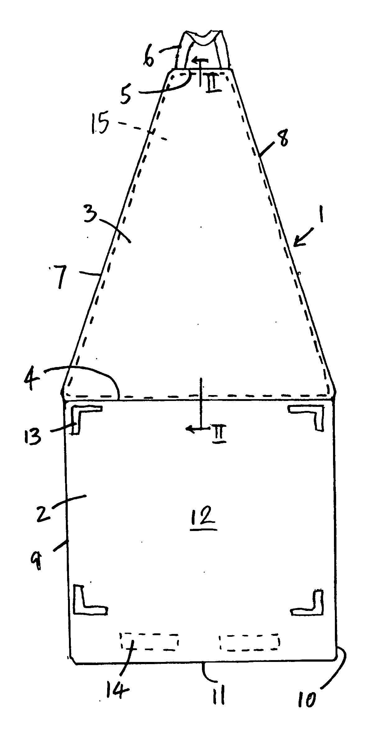
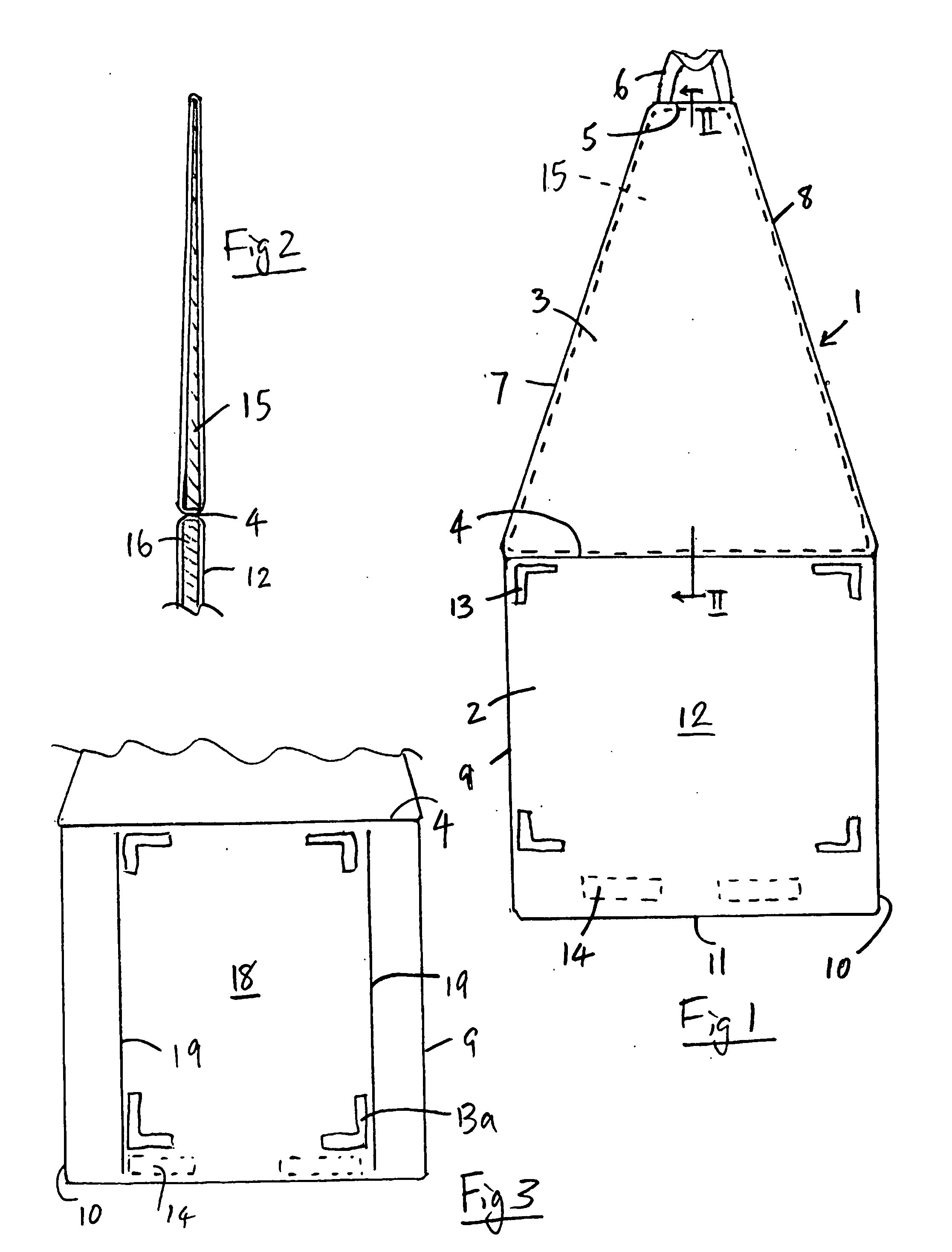
[0020] As can best be seen from FIG. 1, a positioning device according to the present invention for use in radiography to position an X-ray cassette or a radiographic grid and X-ray cassette beneath a patient lying upon a bed or other support to enable an X-ray image of a portion of the patient to be taken essentially comprises a plastics envelope 1 defining first and second envelope sections 2,3 separated from each other by a common edge 4. As can be seen from FIG. 1, the first envelope section 2 is generally rectangular in configuration while the second envelope section 3 has the shape of a trapezium or truncated triangle the width of which narrows from edge 4 to a minimum width at its furthest edge 5, where a handle 6 formed of cotton or other fabric tape is attached. Although the edges of envelope section 3 are shown as straight lines, they could be curved. The envelope sections are sealed from each other along the common edge 4 and also sealed along their remaining edges 5, 7, ...


PUM


Abstract

An X-ray cassette or a radiographic grid and X-ray cassette is (are) mounted within a device for positioning the cassette or grid and cassette beneath a patient lying upon a bed or other support to enable an X-ray image of a portion of the patient to be taken. The device has a plastics envelope formed of a material that is both substantially radiotranslucent and impervious to water or other biological fluids. This envelope defines first and second envelope sections separated from each other by a common edge. The first envelope section is generally rectangular in configuration and defines an openable pouch in which the X-ray cassette or radiographic grid and X-ray cassette are received. The second envelope section has a stiffening member therein. The second envelope section has its greatest width along the common edge and narrows to a minimum width at its edge furthest from the common edge. The stiffening member within the second envelope section is generally wedge shape in section, whereby the second envelope section has a thickness that tapers from a maximum thickness approximating the thickness of the radiographic grid and X-ray cassette at its greatest width adjacent the common edge to a minimum thickness at the furthest edge.

Description

BACKGROUND OF THE INVENTION [0001] This invention relates to radiography and to problems encountered in positioning a patient in relation to X-ray equipment and in relation to photographic film or digital media adapted for taking an X-ray picture of a portion of the patient. [0002] Patients that are severely ill or are suffering from spinal or pelvic injury are often presented to a radiographer lying upon a bed or other support. In order that an X-ray image may be taken, the photographic film or digital medium, conventionally mounted in an X-ray cassette (together with a radiographic grid when the chest, spine or pelvis are to be imaged) must be positioned beneath the patient so that the patient can be placed beneath a source of X-rays to enable an X-ray image to be taken through a portion of their body. [0003] Specially adapted beds or supports have previously been provided with a hollowed out section into which the radiographic grid and X-ray cassette may be inserted while the pat...

Claims


Application Information

Patent Timeline
IPC IPC(8): G03B42/02
CPCG03B42/025
Inventor REID, PAULLUSCOMBE, IAN
Owner X RAY SLIDER
Why Eureka
Try Eureka