Heat-shrinkable tube fitting jig and method for manufacturing electric wire with heat-shrinkable tube

Active Publication Date: 2018-03-08
AUTONETWORKS TECH LTD +2
View PDF12 Cites 0 Cited by
  • Summary
  • Abstract
  • Description
  • Claims
  • Application Information

AI Technical Summary

Benefits of technology

[0021]Furthermore, according to the fourth aspect, the pair of circumferential surface abutting portions can pinch a counterpart connecting portion to prevent rotation of the counterpart connecting portion after being fitted on the columnar body. In this way, the terminal-attached electric wire can be prevented from rotating.
[0022]Furthermore, according to the fifth aspect, the counterpart terminal can be prevented from rotating by setting the counterpart terminal in the recessed surface after being fitted onto the columnar body. In this way, the terminal can be prevented from rotating.
[0023]Furthermore, according to the sixth aspect, because the first end face of the heat-shrinkable tube can be held down, the heat-shrinkable tube can be more properly positioned.
[0024]Fu

Problems solved by technology

In this way, there is a chance that the attachment of the heat-shrinkable tube may become defective

Method used


Image

  • Heat-shrinkable tube fitting jig and method for manufacturing electric wire with heat-shrinkable tube
  • Heat-shrinkable tube fitting jig and method for manufacturing electric wire with heat-shrinkable tube
  • Heat-shrinkable tube fitting jig and method for manufacturing electric wire with heat-shrinkable tube

Examples


Example

First Embodiment

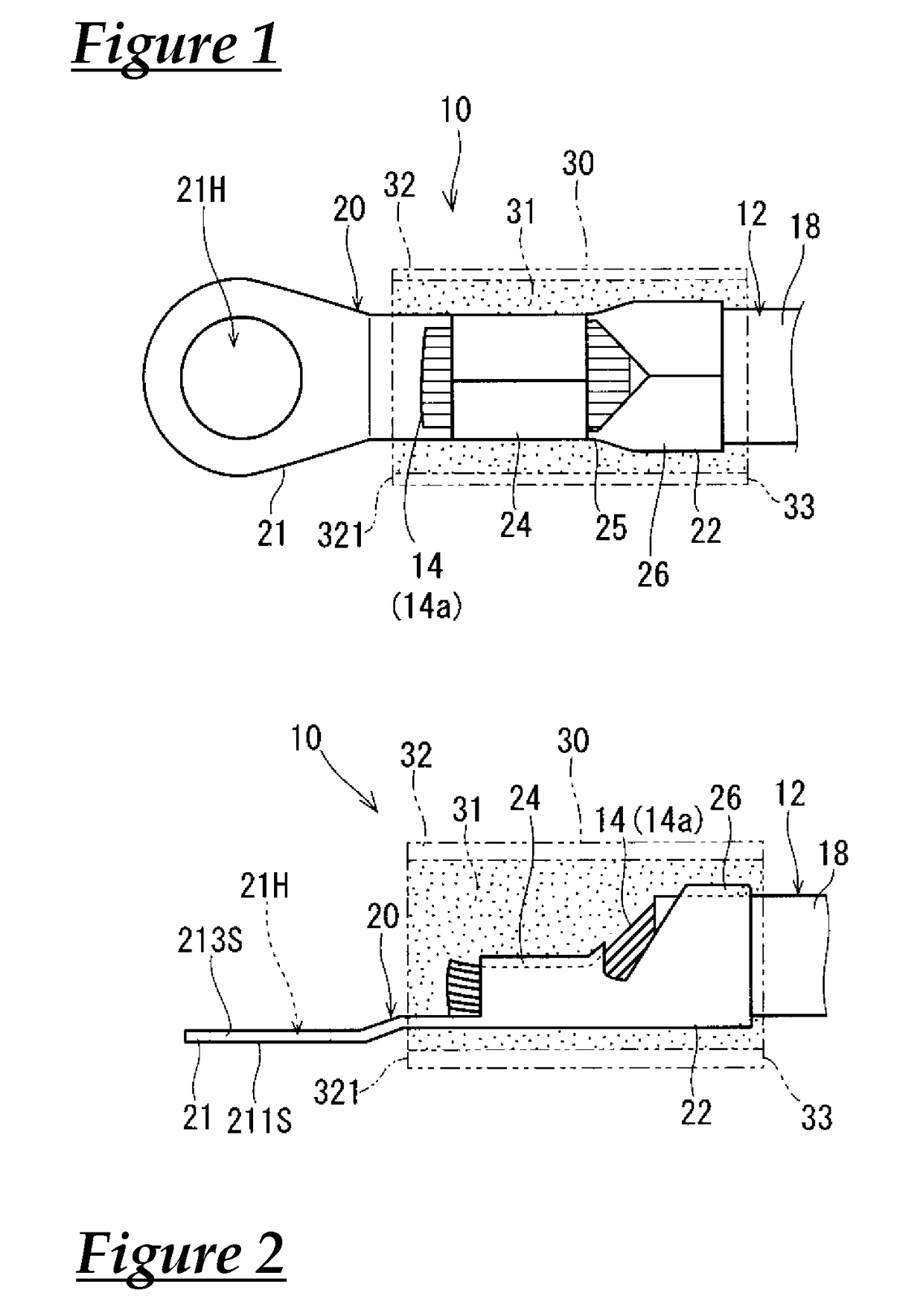
[0039]FIG. 1 is a schematic top view showing a terminal-attached electric wire 10 according to a first embodiment. FIG. 2 is a schematic side view showing the terminal-attached electric wire 10 according to the first embodiment. As shown in FIGS. 1 and 2, the terminal-attached electric wire 10 is provided with an electric wire 12 and a terminal 20.

[0040]The electric wire 12 is provided with a core wire 14 and a sheath 18 that covers the core wire 14. The core wire 14 is a linear conductor formed, for example, by twisting together a plurality of element wires. The sheath 18 is made of an insulating material, such as resin. The sheath 18 is formed, for example, by performing extrusion coating of a softened resin around the core wire 14.

[0041]Furthermore, a predetermined length of the sheath 18 is stripped from the core wire 14 on one end of the electric wire 12. This provides an exposed core wire portion 14a at which the predetermined length of the core wire 14 is expo...

Example

Second Embodiment

[0073]A second embodiment will be described hereinafter. It should be noted that in the description that follows, detailed description of the elements having identical functionality to that of the elements that have been described may be omitted by denoting these elements with identical numerical symbols or identical numerical symbols suffixed with an alphabetical letter.

[0074]FIG. 9 is a schematic top view that shows a heat-shrinkable tube fitting jig 100A according to the second embodiment. The heat-shrinkable tube fitting jig 100A has an approximately identical configuration to that of the heat-shrinkable tube fitting jig 100. However, the heat-shrinkable tube fitting jig 100A differs from the heat-shrinkable tube fitting jig 100 by having a first side abutting plate 40A instead of the first side abutting plate 40.

[0075]FIG. 10 is a schematic perspective view that shows the first side abutting plate 40A according to the second embodiment. A plurality of terminal ...


PUM


Abstract

A heat-shrinkable tube fitting jig is used to fit a heat-shrinkable tube onto a terminal-attached electric wire formed by crimping a core wire crimp portion of a terminal onto a core wire of an electric wire. The heat-shrinkable tube fitting jig is provided with a first side abutting plate, a second side abutting plate member, and an electric wire holding portion. Columnar bodies and recessed surfaces, which constitute terminal positioning portions, are provided on the upper surface of the first side abutting plate. A first side end face and a second side end face of the heat-shrinkable tube are abutted against mutually opposing surfaces (a first side abutting surface 40S and a second side abutting surface 44S) of the first side abutting plate and the second side abutting plate.

Description

CROSS REFERENCE TO RELATED APPLICATIONS[0001]This application claims the priority of Japanese patent application JP2015-059067 filed on Mar. 23, 2015, the entire contents of which are incorporated herein.TECHNICAL FIELD[0002]The present invention relates to technology for fitting a heat-shrinkable tube onto a terminal-attached electric wire.BACKGROUND ART[0003]Patent Document 1 and Patent Document 2 disclose techniques for, when fitting a heat-shrinkable tube onto a connecting portion between an electric wire and a terminal, preventing the hot melt provided inside the heat-shrinkable tube from running over to the counterpart connecting portion of the terminal.[0004]Patent Document 1 (JP2006-261065A) discloses an earth terminal holder that includes a base body for receiving an earth terminal whose crimp connecting portion crimped to a wire harness is covered with a hot melt heat-shrinkable tube, a holding means capable of opening and closing relative to the base body to press and hol...

Claims


Application Information

Patent Timeline
IPC IPC(8): H01R43/20H01R4/18H01R4/72H01R11/12
CPCH01R43/20H01R4/185H01R4/72H01R11/12H01R43/005
Inventor SUDOU, HIROSHIAOI, HAYATO
Owner AUTONETWORKS TECH LTD
Why Eureka
Try Eureka