
Load supporting blocking member for use in a metal stud wall

Active Publication Date: 2014-10-02
BAILEY METAL PROD
View PDF1 Cites 2 Cited by
  • Summary
  • Abstract
  • Description
  • Claims
  • Application Information

AI Technical Summary

Benefits of technology

The present invention provides a load supporting blocking member for use in a metal stud wall. This member has a base that overlies a horizontal bridging member and an upstanding flange that extends from the base. The depth of the base is sufficient to overlay the bridging member and properly position the flange in line with the edges of the studs in the wall. The base has a downwardly extending tab to position the blocking member within the wall cavity. The base also has cut outs adjacent to the flange to allow for the passage of wiring and other services through the base. The technical effect of the invention is to provide a reliable and efficient load supporting member for use in metal stud walls, which provides proper positioning of the blocking member and allows for the passage of various services through the base.

Problems solved by technology

Such walls constructed of the heavier gauge steel are more expensive both in terms of the cost of the steel from which the studs and track are manufactured as well as in the time required to handle the heavier gauge member and to construct the wall, as such walls require heavier duty fastening systems and owing to the thickness of the metal require more time to install the fastenings compared to the lighter gauge non-loading bearing members.
Heavier gauge metal also has the drawback of having better sound transmission and requires more layers of wallboard to maintain the desired reduced sound transmission properties.

Method used


Image

  • Load supporting blocking member for use in a metal stud wall
  • Load supporting blocking member for use in a metal stud wall
  • Load supporting blocking member for use in a metal stud wall

Examples


Embodiment Construction

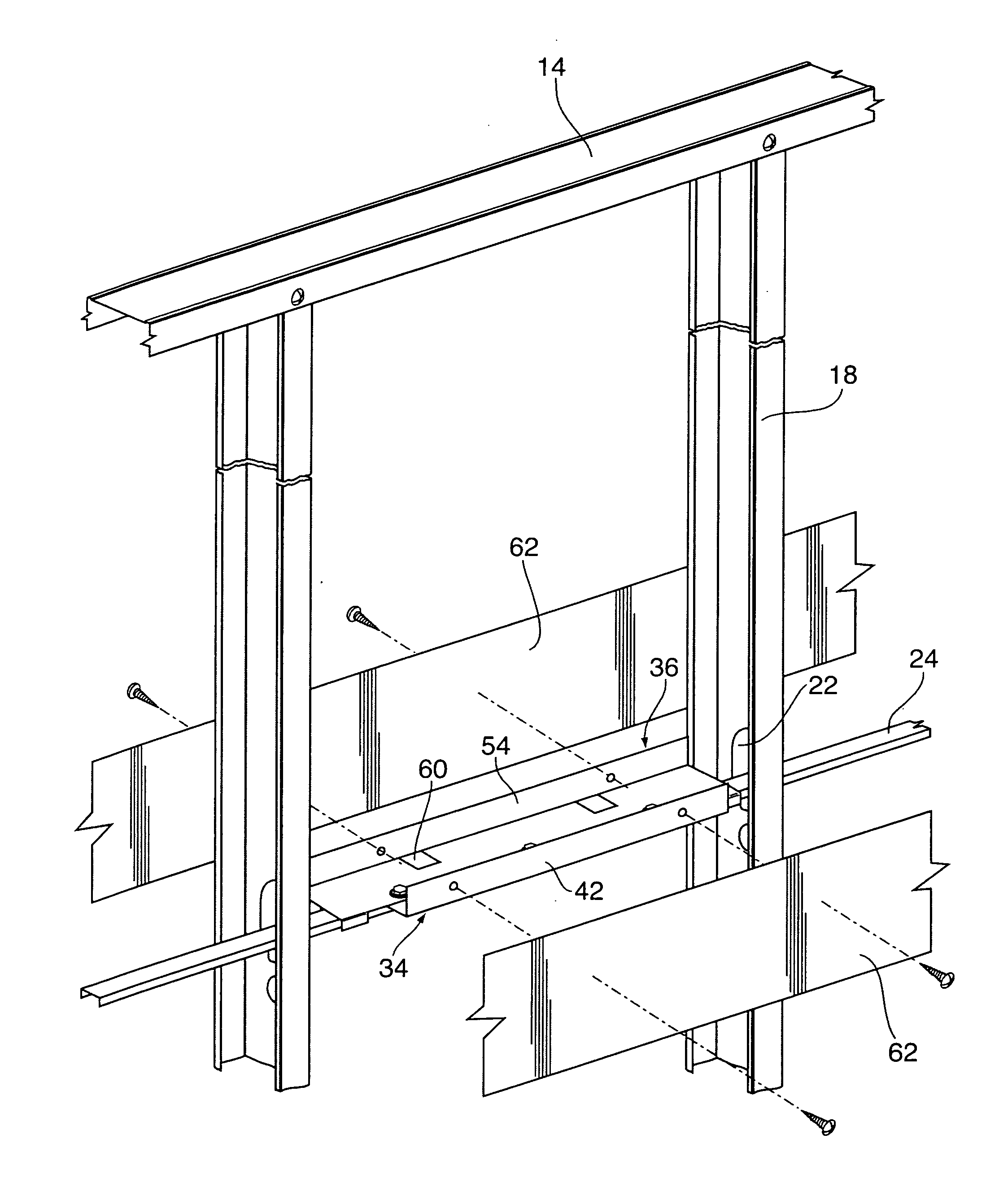
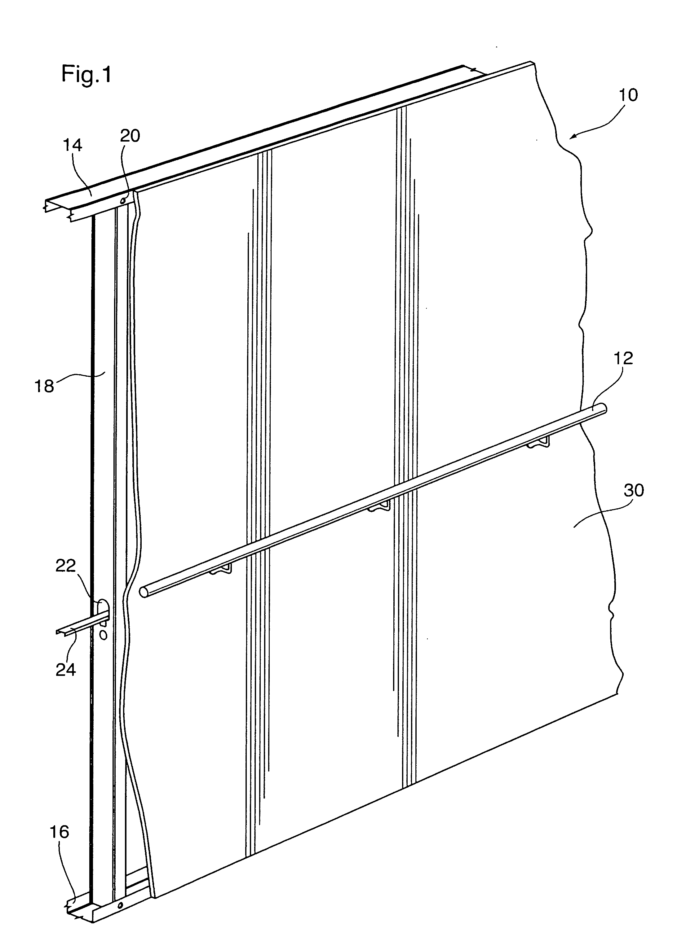
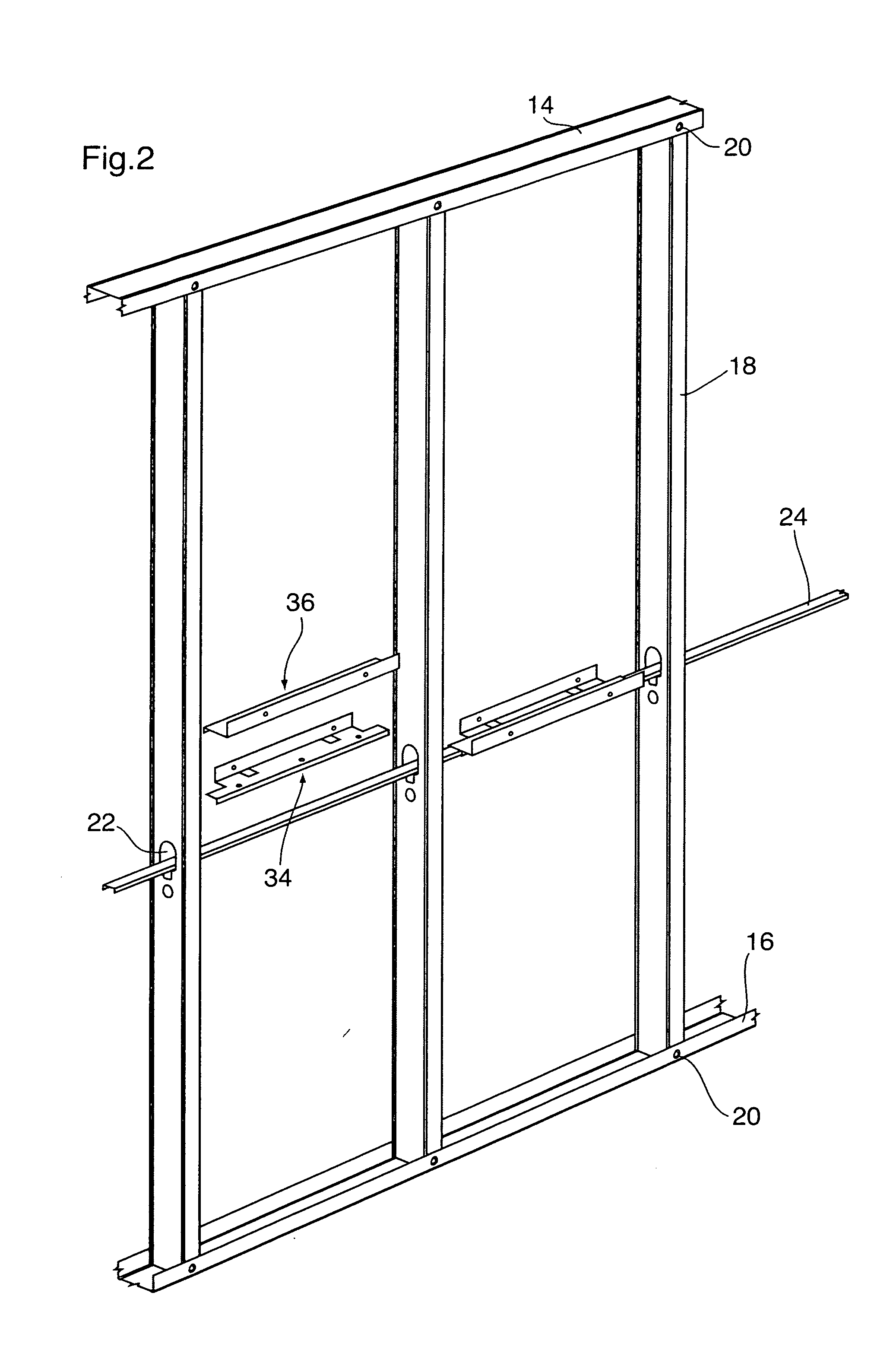
[0021]FIG. 1 illustrates a metal stud wall constructed utilizing a preferred embodiment of a blocking member of the present invention to support a fixture such as a hand rail attached to the wall. The metal stud wall 10 is constructed of a top track 14 attached to a ceiling and a bottom track 16 attached to the floor. A plurality of metal studs 18 are installed vertically within the top track 14 and bottom track 16 evenly spaced along the wall 10. The spacing of the studs is typically 16 or 24″ on center. The studs 18 are attached to the top track 14 and bottom track 16 through the use of suitable fasteners 20. The studs 18 are provided with a first opening 22 which allows for a bridging member 24 to be passed through the opening and attached to the web of the stud 18 by friction fit to provide axial support for the studs 18. A second opening 28 may also be provided in the stud for the passage of services such as wiring or plumbing through the studs within the wall. While the drawin...


PUM


Abstract

The present invention is directed to a load supporting blocking member for use in a metal stud wall having a plurality of parallel spaced apart metal studs, each of the studs having an aligned opening and horizontal bridging member passing through the aligned openings and tying the studs together. The load supporting blocking member comprises a base for overlying and being attached to the bridging member and an upstanding flange extending from one edge of the base the depth of the base being sufficient to overly the bridging member and position the upstanding flange in line with the edges of the studs in the metal stud wall.

Description

FIELD OF THE INVENTION[0001]The present invention relates to a load supporting blocking member for use in a metal stud wall to transfer load from an object mounted on the surface of the wall to the metal studs.BACKGROUND OF THE INVENTION[0002]It is common practice in both commercial and residential buildings to separate and define rooms using partition walls. In most commercial buildings, these walls are typically constructed of metal studs. The metal stud wall typically has a top track located horizontally at ceiling level, a bottom track located horizontally along the floor and vertically parallel stud members spaced evenly throughout the length of the wall secured between the top track and bottom track. Typically for non-loading bearing interior partition walls, the studs and tracks are constructed of 22 to 26 gauge steel which provides for sufficient structure to support the drywall mounted to the outside of the stud wall. For load bearing walls, either walls where the wall is r...

Claims


Application Information

Patent Timeline
IPC IPC(8): E04B1/24
CPCE04B2001/2457E04B1/2403E04B2/7457E04B2/763E04B2002/7485E04F11/1804
Inventor RICE, JOHN
Owner BAILEY METAL PROD
Learn More