
Long reach press

a long-range, press technology, applied in the field of presses, can solve the problems of inconvenient and time-consuming and labor-intensive to move the work piece onto the fixed lower tooling, high cost of dual-stroke hydraulic cylinders,

Active Publication Date: 2005-10-13
BOATRIGHT JEFF +2
View PDF11 Cites 5 Cited by
  • Summary
  • Abstract
  • Description
  • Claims
  • Application Information

AI Technical Summary

Benefits of technology

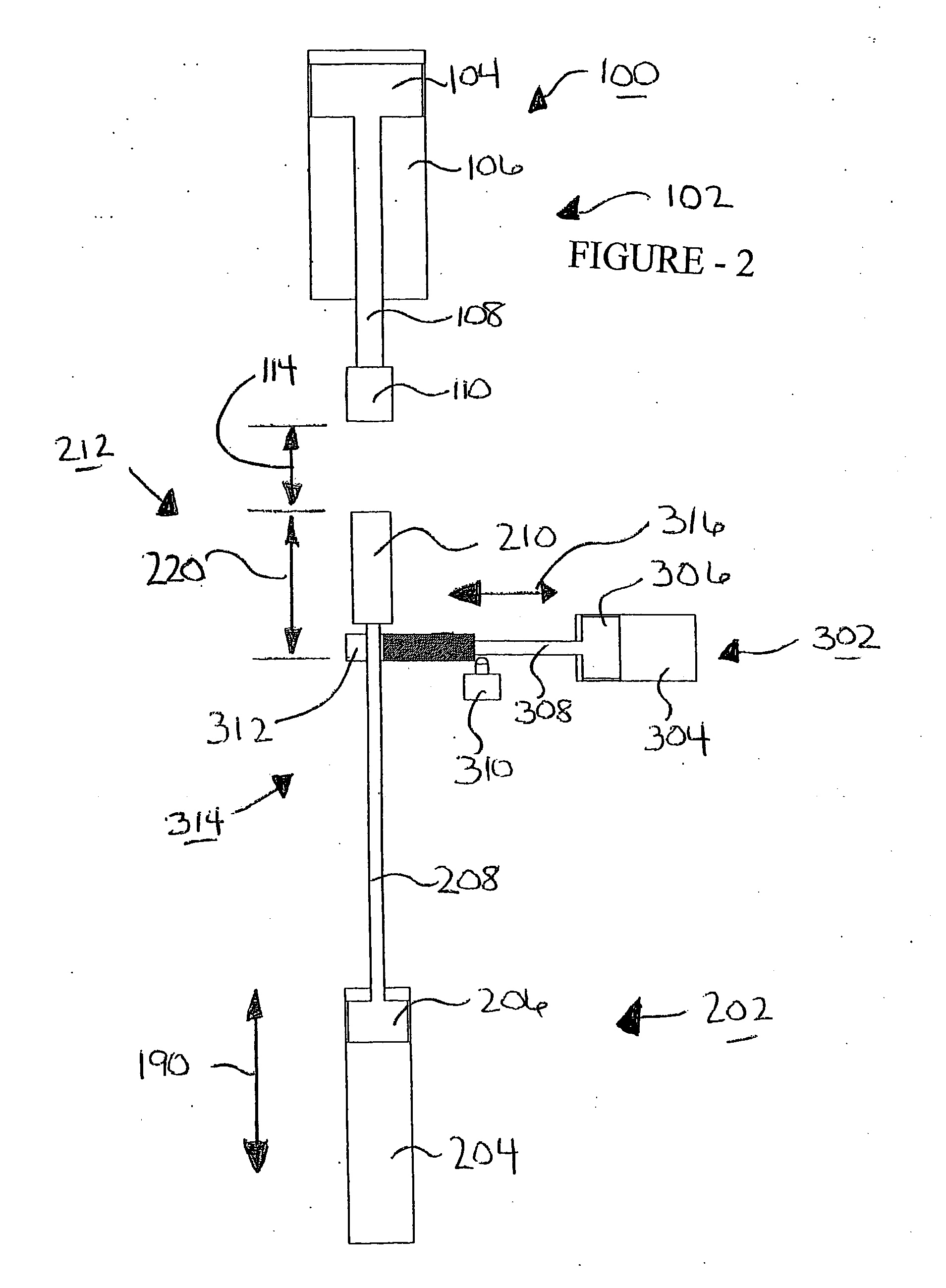
[0010] Wherein said low force means further including a positive stop actuator which includes a slide block stop, wherein said slide block stop can be extended between a stop extended position and a stop retracted position, wherein the stop extended position and the tooling in the lower tooling raised position, the lower tooling is prevented from moving downwardly against the slide block stop.
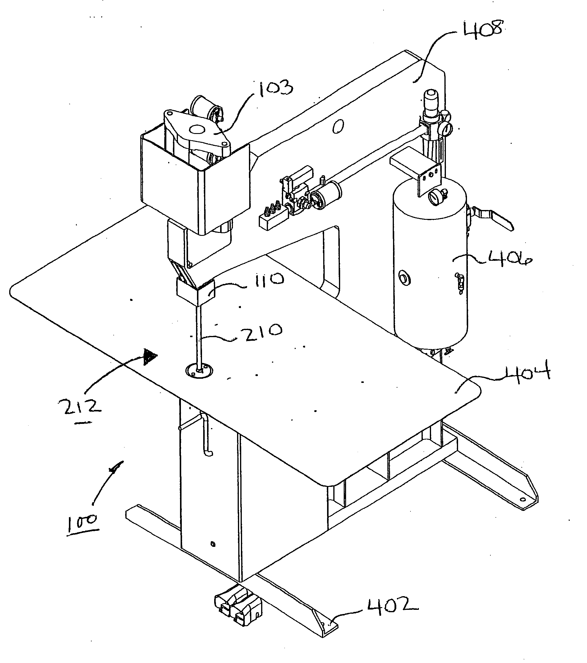
[0029] Preferably, wherein the lower tooling when in the lowered position is retracted below a working table such that the work piece can be easily slid over top of the lower tooling.
[0041] Preferably, wherein said low force means further including a positive stop actuator which includes a slide block stop, wherein said slide block stop can be extended between a stop extended position and a stop retracted position, wherein the slide block stop in the stop extended position and the lower tooling in the raised position, the lower tooling is prevented from moving downwardly past the slide block stop.

Problems solved by technology

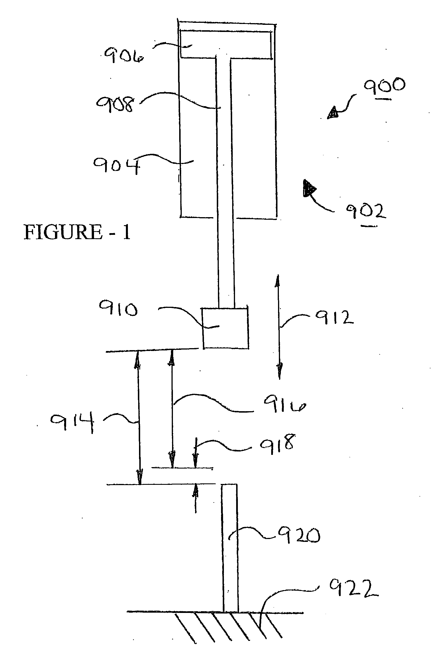
The disadvantages of prior art press 900 as shown in FIG. 1 are the expensive dual stroke hydraulic cylinder 904 that is required along with the sophisticated control system necessary in order to move upper tooling 910 through the low force stroke portion 916 and as well as the high force stroke portion 918.
Secondly, there is the issue of safety, particularly of concern is injury to personnel using prior art press 900.
Thirdly, it is very inconvenient and time consuming and labour intensive to move the work piece onto the fixed lower tooling 920 and generally speaking manual labour must be employed in order to lift parts, such as channel members manually over top of lower tooling 920 so that it can be presented to upper tooling 910.

Method used


Image

  • Long reach press
  • Long reach press
  • Long reach press

Examples


Embodiment Construction

[0057]“High Force”=Normally greater than 100 lb force [0058] For clinching operations normally greater than 1000 lb force is used and typically closer to 5000 lbs force is employed.

[0059]“Low Force”—Normally less than 100 lb force, and typically 30 lbs force is employed in order to avoid operator injury.

[0060] Prior Art

[0061] Referring first of all to FIG. 1 which shows a prior art press shown generally as 900. Prior art press 900 includes a high and low force actuator 902 comprised of a single hydraulic cylinder 904, piston 906, piston rod 908 having attached on one end thereof upper tooling 910. In order to achieve the long reach required, high and low force actuator 902 moves through a long upper stroke 914 which is comprised of both a low force stroke portion 916 and a high force stroke portion 918 as depicted in FIG. 1. In other words, hydraulic cylinder 904 advances upper tooling 910 through a very long upper stroke 914 in two stages. Firstly it advances upper tooling 910 u...


PUM

PropertyMeasurementUnit
Forceaaaaaaaaaa

Abstract

The present invention is a long reach press comprising a low force actuator for operably urging first tooling into a working position. It further includes an opposed high force actuator for operably urging second tooling into engagement with the first tooling. The low force actuator includes a positive stop actuator including a slide block stop for operatively supporting and restraining movement of the first tooling when engaged with the second tooling. The slide block is moveable between a stop extended position and a stop retracted position.

Description

[0001] The present application claims priority from previously filed Provisional Application 60 / 586,223 filed Jul. 9, 2004 as well as U.S. Provisional 60 / 561,527 filed Apr. 13, 2004.FIELD OF THE INVENTION [0002] The present invention relates to presses and in particular relates to pneumatic hydraulic and air operated long reach presses. BACKGROUND OF THE INVENTION [0003] Presses are used for stamping, punching, clinching, nut insertion, shearing and other functions on metals and other materials. Presses generally are designed to impart forces onto working materials and these forces are generated through mechanical, hydraulic, pneumatic or air actuated devices. Specialized presses have been developed for working with parts that have particularly deep sections, such as channel letters. Channel letter for example have a back plate which is clinched to a side wall producing a deep and wide U- channel which is then used for production of letters of various shapes. These channel letters c...

Claims


Application Information

Patent Timeline
IPC IPC(8): B21J9/02B21J9/12B21J13/00B21J13/04B30B1/00B30B1/32B30B9/00
CPCB21J9/02B21J9/12B21J13/04B30B1/323Y10T29/49915
Inventor BOATRIGHT, JEFFSMITH, QUINNSELORME, BYRON
Owner BOATRIGHT JEFF
Learn More