Finger plucker lock

a technology of finger and lock, which is applied in the field of finger plucker locks, can solve the problems of operator making a large initial capital expenditure, not easy to replace fingers, and minimal additional space, and achieve the effect of easy inserting and removing plucking fingers

Inactive Publication Date: 2006-06-27
TURNER RODNEY ALLEN
View PDF10 Cites 6 Cited by
  • Summary
  • Abstract
  • Description
  • Claims
  • Application Information

AI Technical Summary

Benefits of technology

[0013]Briefly described, the present invention is a novel support disc and rubber finger structure that allows an operator to easily insert and remove plucking fingers from the support disc without the application of excessive force. Furthermore, the operator is not required to contort himself into strange and uncomfortable positions in order to access the picking fingers. Replacement is accomplished easily and comfortably.
[0014]The novel rubber plucking fingers of the present invention do not have the annular recess and oversized shank that was present in the fingers of the prior art. The fingers can easily be slid through the corresponding holes in the support plate, without the requirement that excess force be used in order to properly seat the annular recess about the hole edge. The rubber finger is therefore only comprised of an oversized base to prevent the finger from being pulled entirely through the support plate hole, and a tapered furrowed shank. The diameter of the shank proximate the base is substantially equal to the diameter of the hole to ease insertion and removal. The diameter of the shank is therefore such that the picking finger can easily rest securely in the support hole, but backward movement of the finger can be easily accomplished with only minimal force being applied. The annular recess should not be confused with the gripping rings or protrusions, which are located remote from the oversized base, as such are provided to increase frictional forces between the finger and the feathers, and have nothing to do with the retention of the finger within the support base.
[0015]In order to prevent unwanted movement of the finger within the hole, and possible dislodgement therefrom, a backing plate is provided to abut the rear of the support plate and hold the finger securely. The backing plate is attached to the rotatable shaft so that the backing plate abuts the oversized base of the rubber fingers, preventing accidental displacement of the rubber finger from the support plate. The support plate is attached to the backing plate using an integrated locking mechanism.
[0018]It is another object of the current invention to provide an improved resilient rubber finger that can be easily inserted into and removed from apertures in a support disc.
[0019]It is another object of the current invention to provide an improved resilient rubber finger that can be retained within the support disc without the inclusion of an annular recess in the finger's shank.
[0021]It is another object of the current invention to provide a new support disc assembly for use with resilient rubber finger in the plucking of feathers from poultry wherein the new support disc assembly includes a backing plate to prevent the rubber fingers from becoming dislocated through the rear of the support disc.

Problems solved by technology

However, such additional space seems minimal, with the invention being directed to optimization of feather removal, not ease of finger replacement.
Additionally, this would require the operator to make a large initial capital expenditure to install the rotating banks.
While useful in inserting the fingers, this device does nothing to simplify removal.
Furthermore, ergonomic and space issues are compounded when an operator is trying to maneuver this apparatus into the confined space allowed by most plucking apparatuses.
Problems inherent to the prior art of inserting and removing the rubber fingers are still present.
While useful in inserting the fingers, this device does nothing to simplify removal.
Furthermore, ergonomic and space issues are compounded when an operator is trying to maneuver this apparatus into the confined space allowed by most plucking apparatuses.

Method used


Image

  • Finger plucker lock
  • Finger plucker lock
  • Finger plucker lock

Examples


Embodiment Construction

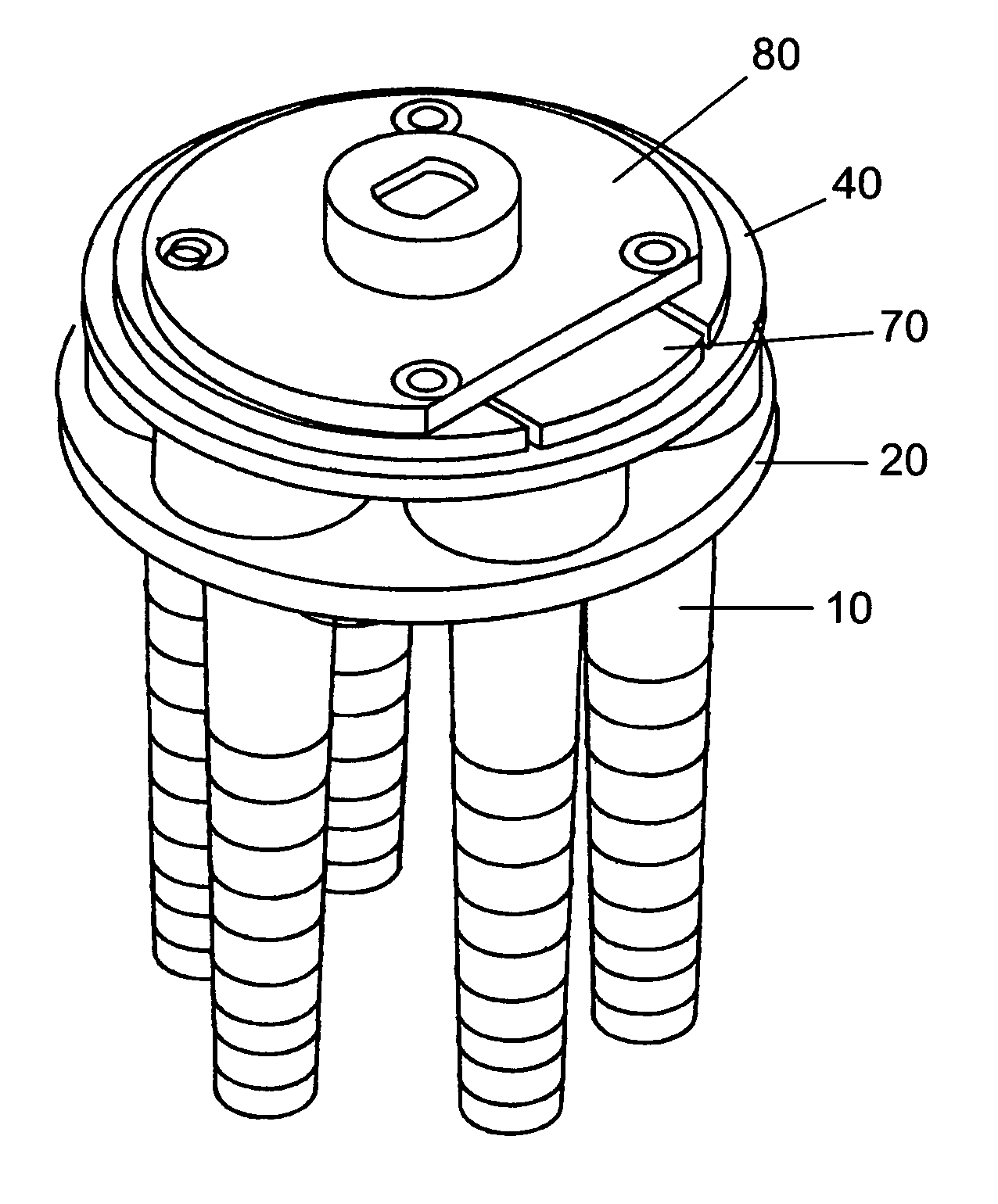
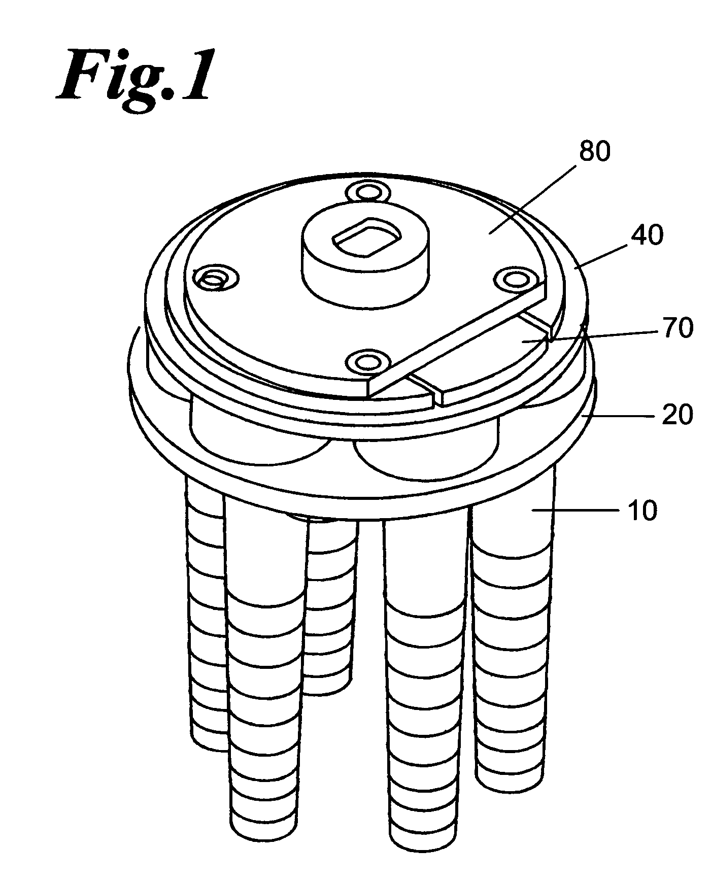
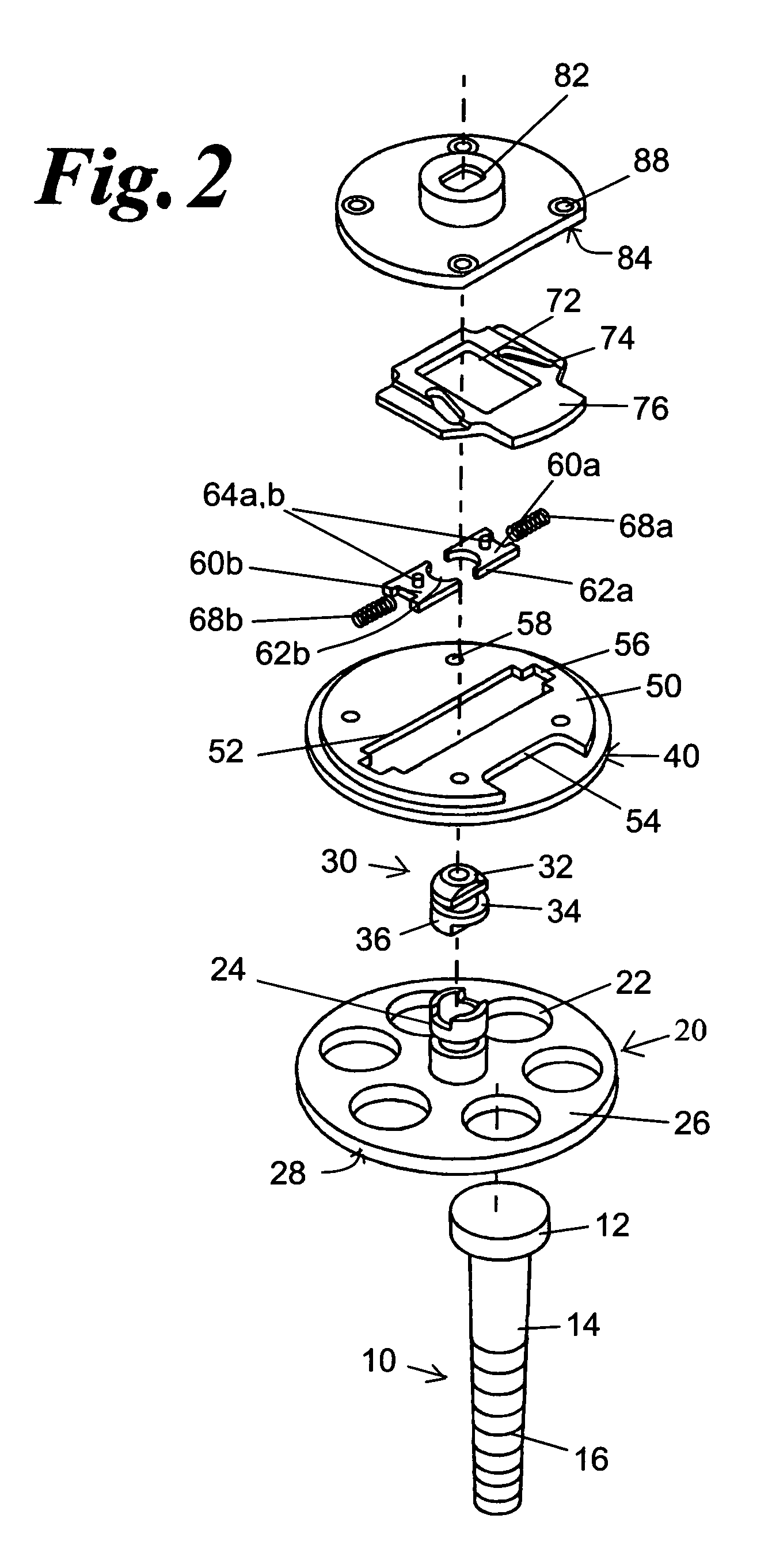
[0034]Referring now to the drawings, and particularly to FIGS. 1, 2, and 4, fingers 10 are generally made of a natural rubber, or a synthetic material, that provides adequate friction to effectively remove feathers from the poultry carcass, but also pliable enough so that the carcass is not damaged from repeated impacts by the spinning fingers. Suitable materials include, but are not limited to natural rubbers, synthetic rubbers including, but not limited to, Styrene-butadiene rubber, Isoprene rubber, Butadiene rubber, Ethylene-propylene rubber, Butyl rubber, Chloroprene rubber, Nitrile rubber, and combinations thereof. It is further contemplated that the natural and synthetic rubber compositions can include various additives, such as tackifiers, pigments, anti-oxidants, anti-UV, etc., and all of such are contemplated, and do not effect the scope of the present invention.

[0035]The fingers themselves comprise an enlarged base 12, and a tapered shank 14. The base 12 prevents the shank...


PUM


Abstract

A resilient rubber finger and a locking mechanism therefore for use in poultry processing plants for the plucking of feathers off if poultry is provided. The rubber-plucking finger is comprised of an oversized base without an annular recess, and a tapered furrowed shank. A plurality of fingers is inserted into a support base through apertures therein. The diameter of the shank proximate the base is substantially equal to the diameter of the support base aperture to ease insertion and removal. A backing plate is provided to abut the rear of the support plate preventing accidental displacement of the rubber finger from the support plate. The support plate is attached to the backing plate using an integrated centrifugal locking mechanism within the backing plate.

Description

CROSS-REFERENCE TO RELATED APPLICATION[0001]This application claims the benefit of the Provisional Patent Application Ser. No. 60 / 559,174 filed on Apr. 2, 2004.FIELD OF THE INVENTION[0002]This invention relates generally to equipment used in connection with poultry feather picking machines, and particularly to a method of mounting and securing a resilient picking finger in a poultry feather-plucking device.BACKGROUND OF THE INVENTION[0003]Machines have been developed for plucking the feathers of poultry for use in poultry processing plants. These picking machines typically have drums and / or discs to which resilient rubber or synthetic picker fingers are mounted. The drums or discs are positioned along each side of a path of travel along which birds are conveyed. The drums or discs are then rotated at speeds as high as 600 to 1250 rpm causing the resilient fingers to be constantly driven into contact with the birds. Frictional forces between the rubber fingers and the feathers remove...

Claims


Application Information

Patent Timeline
Patent Type & Authority Patents(United States)
IPC IPC(8): A22C21/02
CPCA22C21/022
Inventor TURNER, RODNEY ALLEN
Owner TURNER RODNEY ALLEN
Why Eureka
Try Eureka