Mower discharge sliding door

a technology of sliding door and mulching plate, which is applied in the direction of mowers, agriculture tools and machines, agriculture, etc., can solve problems such as messing on lawns, and achieve the effect of easy installation or removal

Inactive Publication Date: 2008-08-05
BLEDSOE DANNY
View PDF24 Cites 6 Cited by
  • Summary
  • Abstract
  • Description
  • Claims
  • Application Information

AI Technical Summary

Benefits of technology

[0007]The present invention is a discharge door or mulch plate for an industrial grade mower that has a cutting blade rotating in horizontal plane under an inverted dish like housing that has a cuttings discharge opening in a side wall of the housing. The removable mulch plate is held in a dual channel receiver mounting system to cover and uncover the discharge opening respectively to mulch and discharge the cuttings. The attachment system is easily retrofitable to older mowers of the above mentioned design as well as capable of being included in a new mower design. The mulch plate is fitted with a handle that is used to easily install or remove it. The design of the handle allows it to act as a positive placement device which secures it at the proper height on the discharge of the mower deck. The present invention also incorporates a curved mulch plate which helps to keep the grass in motion which aids in cutting it into fine pieces before it drops to the ground. Other designs use a flat plate which prevents the discharge of clippings but leaves comers inside the mower deck which gather undesirable clumps of clippings which subsequently fall to the ground in large pieces and cause a mess on the lawn.
[0008]This invention relates generally to an improvement to a removable mulching plate discharge door for industrial grade power lawn mowers having an inverted dish like housing with one or more cutting blades thereunder which, during cutting, rotate in a horizontal plane and discharge the cuttings through an opening in a side wall of the housing. The improvement provides for an assembly for mounting a pair of power mower channel shaped brackets into which the mulch plate slides and is held in place by gravity. The height of the plate is maintained by the handle coming into contact with the mower deck. Moreover, this design may be fabricated as a kit and retrofitted onto an old mower of the proper design. Furthermore, newly manufactured mowers may be fabricated including the assembly enabling the operator to easily insert or remove the mulch plate by simply lifting it out of the channel brackets. Equally important to the design is the curved shape of the mulch plate which enhances mulching and prevents the grass from clumping up under the deck and eventually falling out and making a mess on the mown yard (as with other designs that employ a flat plate rather than one curved to blend in with the shape of the mower deck).
[0009]An object of the present invention is to provide an easily removable mulch plate assembly for mounting to or being incorporated with an industrial type power mower.
[0011]Another object of the present invention is to provide a mulching plate assembly which is can be easily retrofitted to a mower as well as a design which can be incorporated into a new mower design.
[0013]It is another object t of the present invention to provide a removable mulch plate including a curved portion which conforms to the curvature of a mower deck to enhance circulation of the grass clippings and enhancement of the cyclone effect of keeping the clippings where the blades are cutting them rather than allowing the clumping of clippings under the deck at the attachment point of the mulch plate.
[0014]Yet another object of the present invention is to provide a design which improves mulching performance by means of the curved shape of the mulch plate which serves to enhance the cyclone effect to keep the clippings in motion until they are cut into small enough pieces rather than allowing clumping of grass clipping under the deck and a subsequent mess on the lawn.

Problems solved by technology

Other designs use a flat plate which prevents the discharge of clippings but leaves comers inside the mower deck which gather undesirable clumps of clippings which subsequently fall to the ground in large pieces and cause a mess on the lawn.

Method used


Image

  • Mower discharge sliding door
  • Mower discharge sliding door
  • Mower discharge sliding door

Examples


Embodiment Construction

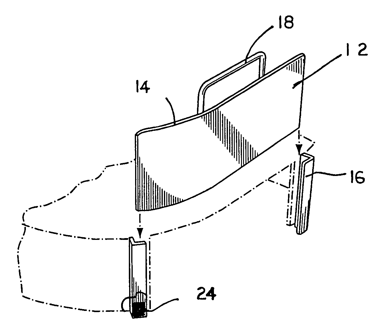
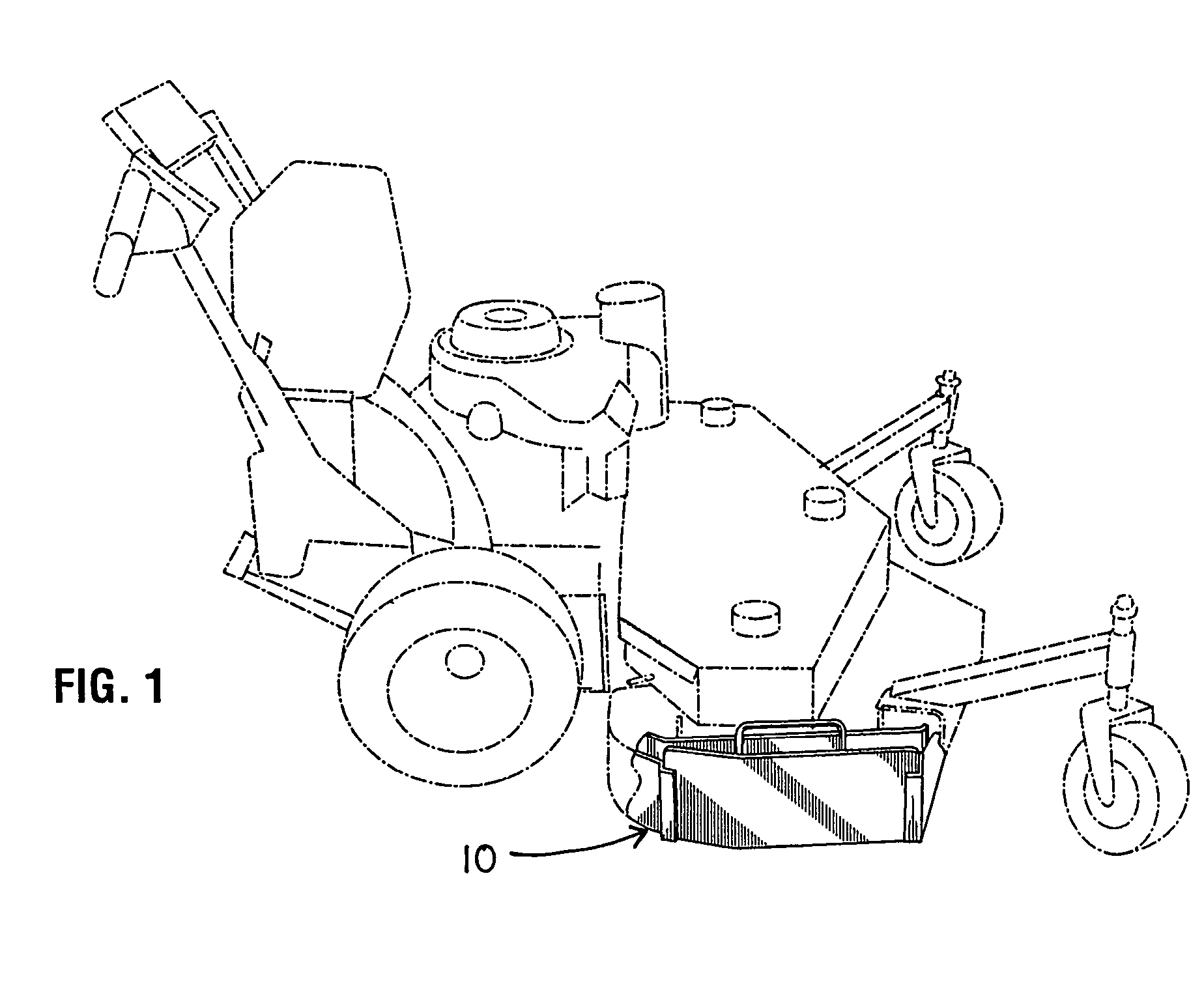
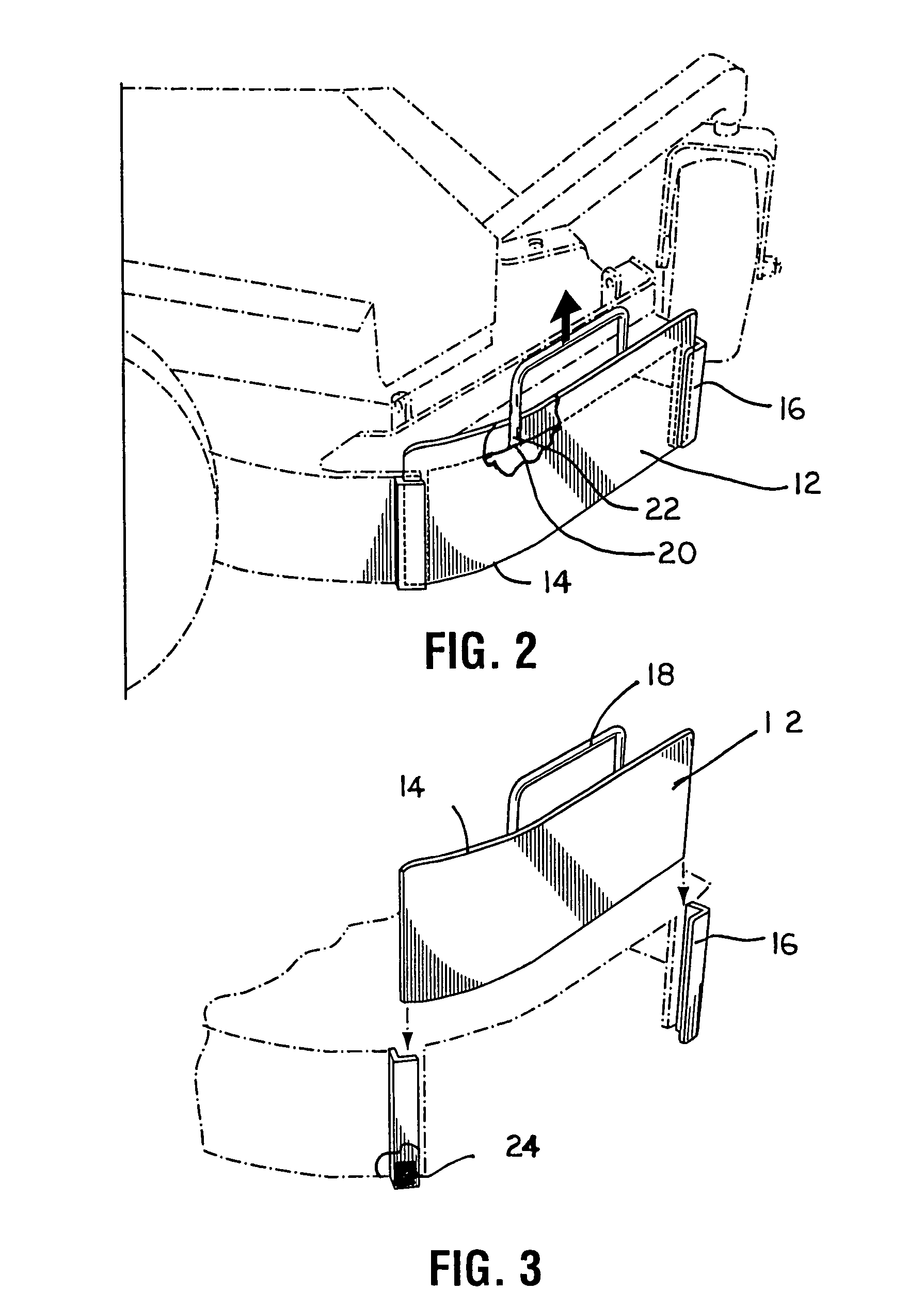
[0022]Referring to the drawings illustrated in FIGS. 1-3, is a 52 inch walk behind lawn mower 10, known commercially under the Trademark ‘SCAG’, having an assembly of the present invention mounted thereon. The power mower is of the type having one or more rotatable cutting elements disposed horizontally below an inverted dish like housing that has a cuttings discharge opening in a side wall of the housing and a rigid frame structure. The dimensions will vary depending upon the make, model and size of the mower and also can be varied to provide the desired movement characteristics.

[0023]A preferred embodiment of the mulch plate assembly 10 is a removable mulch plate 10 comprising a generally rectangular strip of metal formed having a curvature of up to a 90 degree angle at a selected position 14 of about two-thirds of the length of the plate 10 in order that the adapter conform to the mower frame or housing permitting the adapter to be bolted onto the existing mower frame or housing....


PUM


Abstract

An industrial grade mower that has a cutting blade rotating in horizontal plane under an inverted dish like housing that has a cuttings discharge opening in a side wall of the housing, and a easily removable mulch plate held in a dual channel receiver mounting system to cover and uncover the discharge opening respectively to mulch and discharge the cuttings. The mower discharge door or mulch plate attachment system is easily retrofitable to older mowers of the above mentioned design as well as capable of being included in a new mower design. The mulch plate is fitted with a handle that is used to easily install or remove it. The design of the handle allows it to act as a positive placement device which secures it at the proper height on the discharge of the mower deck. The present invention also incorporates a curved mulch plate which helps to keep the grass in motion which aids in cutting it into fine pieces before it drops to the ground.

Description

BACKGROUND OF THE INVENTION[0001]1. Field of the Invention[0002]This invention relates generally to an improvement to a removable mulching plate discharge door for industrial grade power lawn mowers.[0003]2. Description of the Prior Art[0004]Industrial grade power mowers are well known and they may be of the walk behind or ride on type. The cutting swath varies and those with a 52 inch and a 61 inch are quite common whereby the 52 inch is a walk behind and the 61 inch a ride on mower. The housing of these mowers have a discharge opening in a side of the housing that presently require an operator to physically relocate themselves to the discharge opening to change from mulching and discharging the cuttings.[0005]In these mowers the cuttings discharge opening is located forwardly, laterally and downwardly from where the operator is located during cutting. The distance from the operator will vary depending upon the size and / or type of mower. During cutting ground and / or cutting conditi...

Claims


Application Information

Patent Timeline
Patent Type & Authority Patents(United States)
IPC IPC(8): A01D67/00
CPCA01D34/005A01D42/005A01D2101/00
Inventor BLEDSOE, DANNY
Owner BLEDSOE DANNY
Why Eureka
Try Eureka