Non-contact torque determination system and method for a non-mechanically coupled rotating system

a non-contact, rotating system technology, applied in the field of torque determination, can solve the problem of unsuitable methods for determining the torque in an environmentally isolated rotating system with sufficient accuracy

Inactive Publication Date: 2012-05-08
HONEYWELL INT INC
View PDF32 Cites 2 Cited by
  • Summary
  • Abstract
  • Description
  • Claims
  • Application Information

AI Technical Summary

Problems solved by technology

However, because each relies on a component being mechanically coupled, in one fashion or another, to the rotating system, these methods are unsuitable for determining the torque in an environmentally isolated rotating system with sufficient accuracy.

Method used


Image

  • Non-contact torque determination system and method for a non-mechanically coupled rotating system
  • Non-contact torque determination system and method for a non-mechanically coupled rotating system
  • Non-contact torque determination system and method for a non-mechanically coupled rotating system

Examples


Embodiment Construction

[0014]The following detailed description is merely exemplary in nature and is not intended to limit the invention or the application and uses of the invention. Furthermore, there is no intention to be bound by any theory presented in the preceding background or the following detailed description. In this regard, although a particular preferred embodiment is described as being implemented with a test fixture that is used to test bearing assemblies and to measure the drag torque of bearing assemblies, the system and method may be used with and in various other systems, components, devices, and environments.

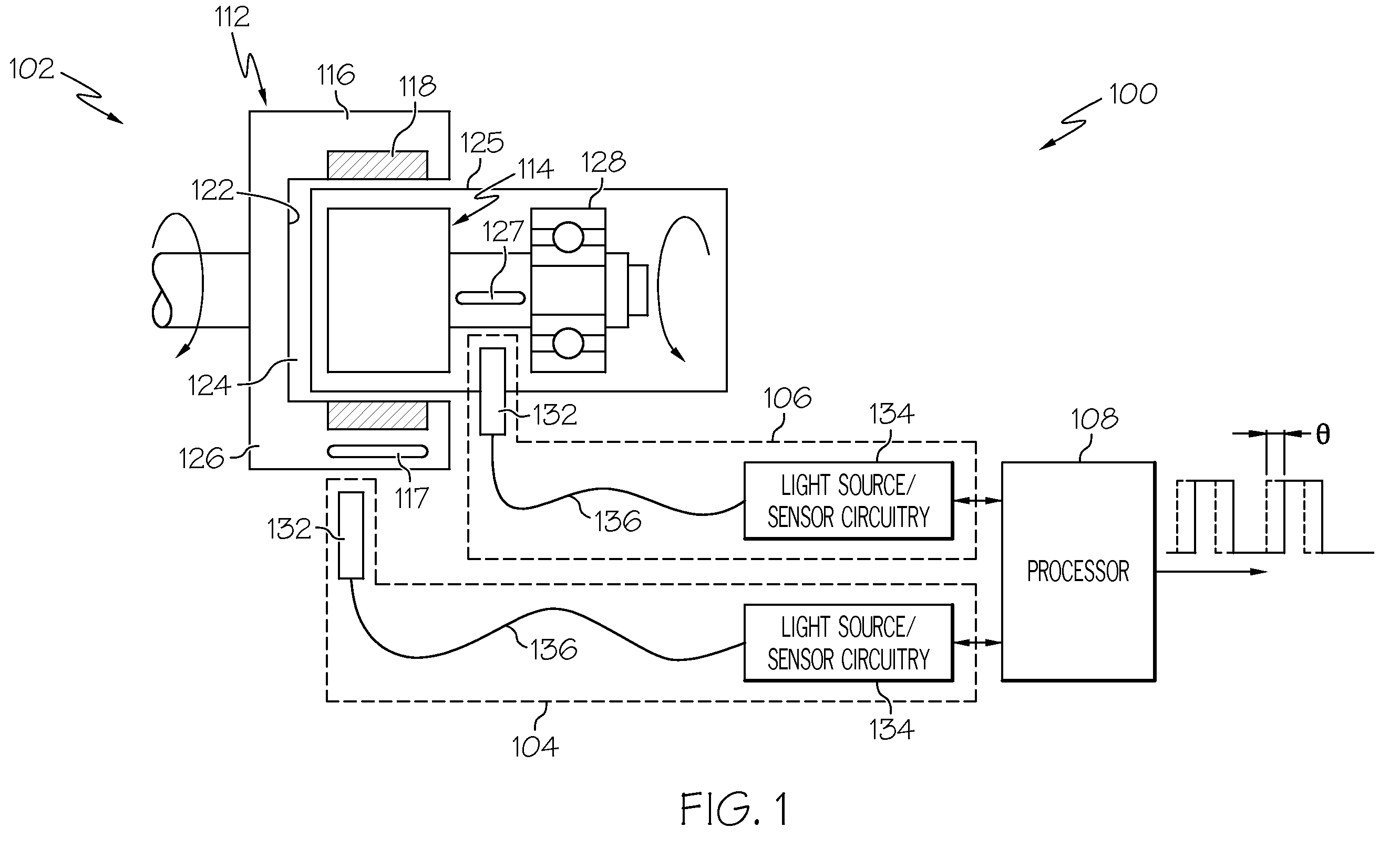
[0015]Referring first to FIG. 1, a functional block diagram of an exemplary non-contact torque determination system 100 is depicted, and includes a magnetic coupling 102, a first optical transceiver 104, a second optical transceiver 106, and a processor 108. The magnetic coupling 102 includes an outer rotor 112 and an inner rotor 114. The outer rotor 112 is responsive to a drive tor...


PUM

PropertyMeasurementUnit
torqueaaaaaaaaaa
inner volumeaaaaaaaaaa
angular stiffnessaaaaaaaaaa

Abstract

Methods and apparatus are provided for determining torque in an environmentally isolated system. A drive system is coupled to the environmentally isolated system via a non-contact, magnetic coupling that has a known angular stiffness and at least two coupling sections. A relative deflection of each coupling section is optically measured, and the torque is determined based on the relative deflection and the known angular stiffness.

Description

TECHNICAL FIELD[0001]The present invention generally relates to torque determination, and more particularly relates to a system and method of determining torque in a non-mechanically coupled rotating system.BACKGROUND[0002]Numerous and varied methods have been derived for determining the torque on a rotating system. Some examples of known methods include the use of magnetic brakes, strain gage transducers, and system drive motor current. To implement the first method, a magnetic brake with a known magnetic field based on a current and associated reaction torque is coupled to a rotary portion of the system. During operation, the current supplied to generate the magnetic field is used to determine the applied torque. To implement the second method, a strain gage transducer is coupled to the rotating portion of the system and signals and power transferred across slip rings. Torque is derived based on the torsional stress in the shaft to which the gage is coupled. To implement the third...

Claims


Application Information

Patent Timeline
Patent Type & Authority Patents(United States)
IPC IPC(8): G01L3/02
CPCG01L3/109G01L3/12
Inventor STEVENS, CARLOS J.
Owner HONEYWELL INT INC
Why Eureka
Try Eureka