Shock mount in environment sensor protector for non-isolated systems

A technology of shock-absorbing brackets and shock absorbers, applied in the direction of instruments, supporting machines, measuring instrument components, etc., can solve problems such as reduction and system errors

Inactive Publication Date: 2017-03-15
HONEYWELL INT INC
View PDF0 Cites 2 Cited by
  • Summary
  • Abstract
  • Description
  • Claims
  • Application Information

AI Technical Summary

Problems solved by technology

This can lead to system errors reducing the variety of applications that can use the isolated system
[0002] Another ob...

Method used


Image

  • Shock mount in environment sensor protector for non-isolated systems
  • Shock mount in environment sensor protector for non-isolated systems
  • Shock mount in environment sensor protector for non-isolated systems

Examples


example 1

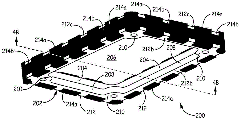
[0040] Example 1 includes a shock mount assembly including a support structure having a geometric configuration, the support structure including at least one side wall and including a first mounting surface, and a shock absorber, the side wall having a structure defining the an outer edge section of the enclosure of the support structure, the first mounting surface is substantially perpendicular to the sidewall, the first mounting surface is configured for coupling at least one electronic device to the support structure, The shock absorber is mounted to at least a portion of the outer edge section, the shock absorber substantially enclosing the enclosure of the support structure, wherein the shock absorber assembly is configured for a non-isolated system, the shock absorber The shock mount assembly is configured to protect electronic equipment during vibration or shock events.

example 2

[0041] Example 2 includes the shock mount assembly of Example 1, wherein the support structure has a circular geometry.

example 3

[0042] Example 3 includes the shock mount assembly of Example 1, wherein the support structure has a rectangular geometry.


PUM


Abstract

The invention discloses a shorck mount in an environment sensor protector for non-isolated sytems. According to the invention, a shock mount assembly for a sensor protector apparatus is provided. The shock mount assembly comprises a support structure having a geometric configuration, with the support structure including at least one side wall having an outer edge section that defines a periphery of the support structure, and at least one mounting surface substantially perpendicular to the side wall. The mounting surface is configured for coupling at least one electronic device to the support structure. A shock absorber is mounted to at least a portion of the outer edge section, with the shock absorber substantially surrounding the periphery of the support structure. The shock mount assembly is configured for a non-isolated system, and is configured to protect the electronic device during vibration or shock events.

Description

Background technique [0001] Inertial sensor systems used in guidance applications are exposed to environments such as vibration, shock and static acceleration. These systems require some form of protection to both function properly and minimize the risk of damage in these environments. Isolation systems are often used to reduce the energy experienced by the sensors during these events, but such isolation systems come with their own disadvantages. In extreme environments, isolation systems can experience displacements beyond their capabilities (ie, sway space) and minimize, which can greatly amplify the input. In these cases, these amplified events can lead to sensor performance degradation and can also lead to component damage, which leads to system failure. Isolation systems also allow inertial sensors to move independently of equipment where they are used for guidance, such as aircraft, missiles, projectiles, trains, ships, cars, etc. This can lead to system errors reduci...

Claims


Application Information

Patent Timeline
IPC IPC(8): G01D11/30G01D11/10G01D11/24
CPCG01D11/10G01D11/245G01D11/30B81B7/0016F16M13/02
Inventor T.L.布拉曼S.J.格普弗特T.特罗斯克
Owner HONEYWELL INT INC
Why Eureka
Try Eureka