Cervical plate system having an insertable rotating element

a cervical plate and insertable technology, applied in the field of cervical plate, can solve the problem that the same rotating element cannot be removed from the slot, and achieve the effect of reducing the number of components, simplifying the surgical procedure, and reducing the difficulty of manipulation

Active Publication Date: 2012-05-08
GUSTILO RAMON B M D +1
View PDF26 Cites 6 Cited by
  • Summary
  • Abstract
  • Description
  • Claims
  • Application Information

AI Technical Summary

Benefits of technology

[0006]Unlike some of the prior art cervical plate systems, the current invention does not involve a locking element that needs to be engaged after a bone screw is inserted in order to keep the bone screw from backing out of the cervical plate. Instead, the surgical procedure is simplified and involves less components, since screw locking is automatically achieved once the screw is fully inserted and tightened. Also, the systems of this invention do not involve tiny components, which can be difficult to manipulate in surgery. Accuracy of the screw trajectories is also ensured since the screws are threaded into the rotating elements, which are incorporated into the plate itself. The present invention also provides a rotating element that is threaded to match the bone screw threads. Meshing between the threads is therefore exact, and the screw can be tightened onto the rotating element to thereby provide more secure locking between the components.
[0007]Another advantage of the current invention is that the possibility of stripping the threads in the bone is minimized or eliminated. In particular, this situation is eliminated using the devices and methods of the present invention because the maximum engagement of the screw threads and the threads on the rotating element determine the maximum seating depth of the screw. Thus, the screw will tighten into the rotating element, and not into the bone.
[0008]In general, the present invention includes a device for stabilizing the cervical spine. It is composed of a plate with two or more slots, a rotating element contained inside each slot, and two bone screws that correspond to each slot and are threadable into the rotating element. Each rotating element can rotate relative to the top and bottom surfaces of the plate. The rotating element has two threaded holes having threads that match the threads of the bone screw. When each bone screw is threaded into the bone, the threads engage the rotating element, locking the bone screw to the rotating element. This prevents the screws from backing out, and at the same time allows the screws to rotate relative to the plate (through the rotating element), thereby allowing “bone graft settling”. The rotating element has outer surfaces that correspond to inner surfaces of the slot in the cervical plate to allow insertion of the rotating element when oriented perpendicular to the top and bottom surfaces of the cervical plate. However, this same rotating element is not removable from the slot when it is oriented or rotated in a generally non-perpendicular orientation relative to the top and bottom surfaces of the cervical plate. In addition, when the bone screws are threaded into the rotating element so that they protrude through the bottom of the cervical plate, the portion of the screw that extends beyond the bottom of the plate can contact the bottom of the plate if the rotating element is rotated a certain amount toward its perpendicular or insertion orientation. In this way, the inserted bone screws serve as a stop or obstruction to rotation of the rotating element back to its perpendicular orientation in which the rotating element would be removable from the cervical plate in which it is inserted.
[0009]In one aspect of the invention, a cervical plate system is provided, which comprises a cervical plate having a thickness between a top surface and an opposite bottom surface, and at least one slot extending through the thickness of the plate. The system further includes a first rotating element positionable within a first slot of the cervical plate, the first rotating element comprising at least one threaded hole, and at least one bone screw insertable into the at least one threaded hole of the first rotating element. The rotating element can have a maximum length that is at least slightly larger than a width of the first slot at a top surface of the cervical plate. The first rotating element can further have a first end and an opposite second end, wherein at least one of the first and second ends has a convex profile, and the first slot in which the first rotating element is positioned can comprise a concave profile at its first and second ends to cooperatively engage with at least one of the first and second ends of the first rotating element. Each bone screw may be positionable so that it extends beyond the bottom surface of the cervical plate and so that each bone screw is in a fixed position relative to the rotatable element and is rotatable relative to the cervical plate. Further, the bone screws may be threaded along their entire length and in at least one embodiment will comprise a head portion that is enlarged relative to a base portion of the screw for preventing rotation of the bone screw beyond a predetermined position.

Problems solved by technology

However, this same rotating element is not removable from the slot when it is oriented or rotated in a generally non-perpendicular orientation relative to the top and bottom surfaces of the cervical plate.

Method used


Image

  • Cervical plate system having an insertable rotating element
  • Cervical plate system having an insertable rotating element
  • Cervical plate system having an insertable rotating element

Examples


Embodiment Construction

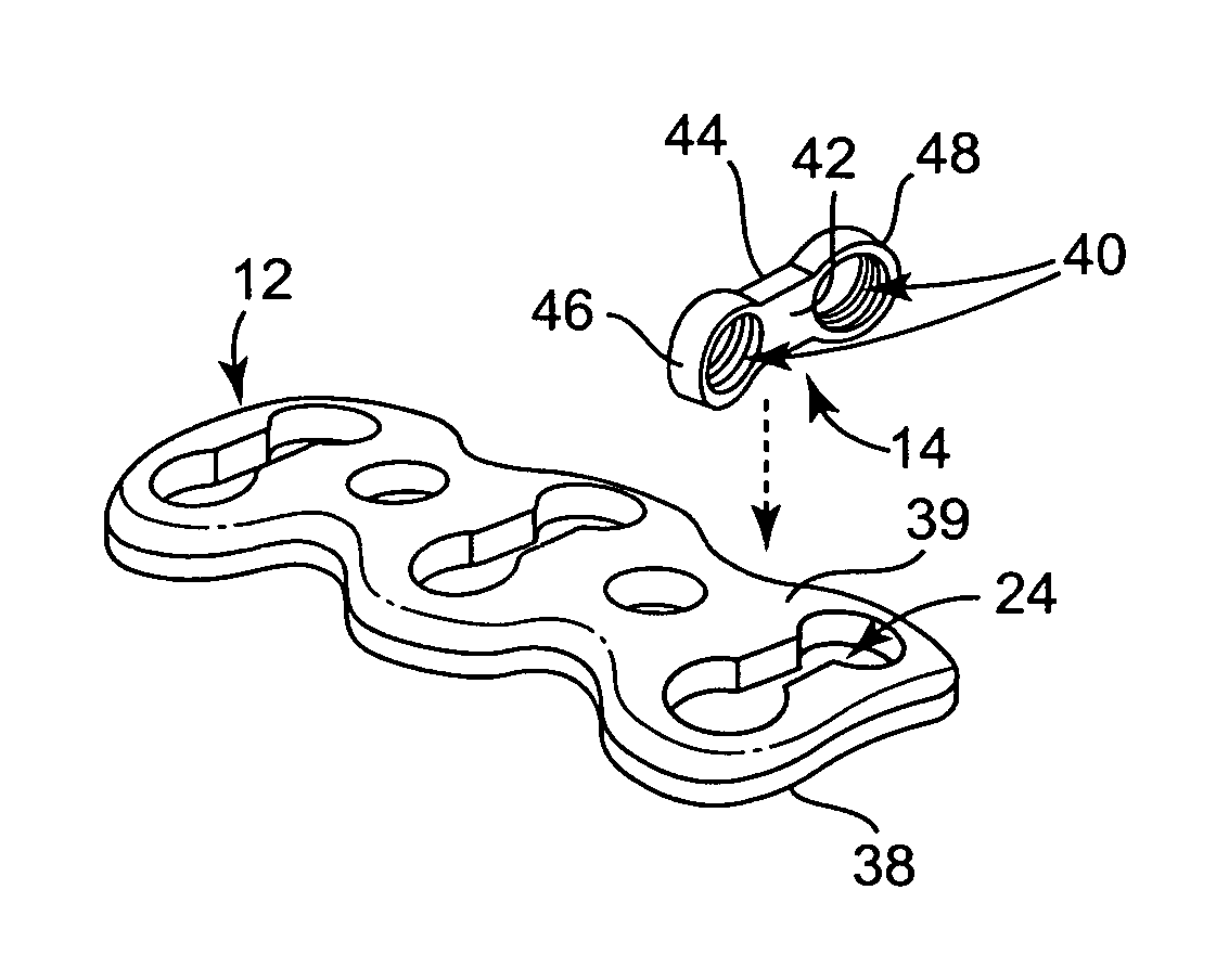
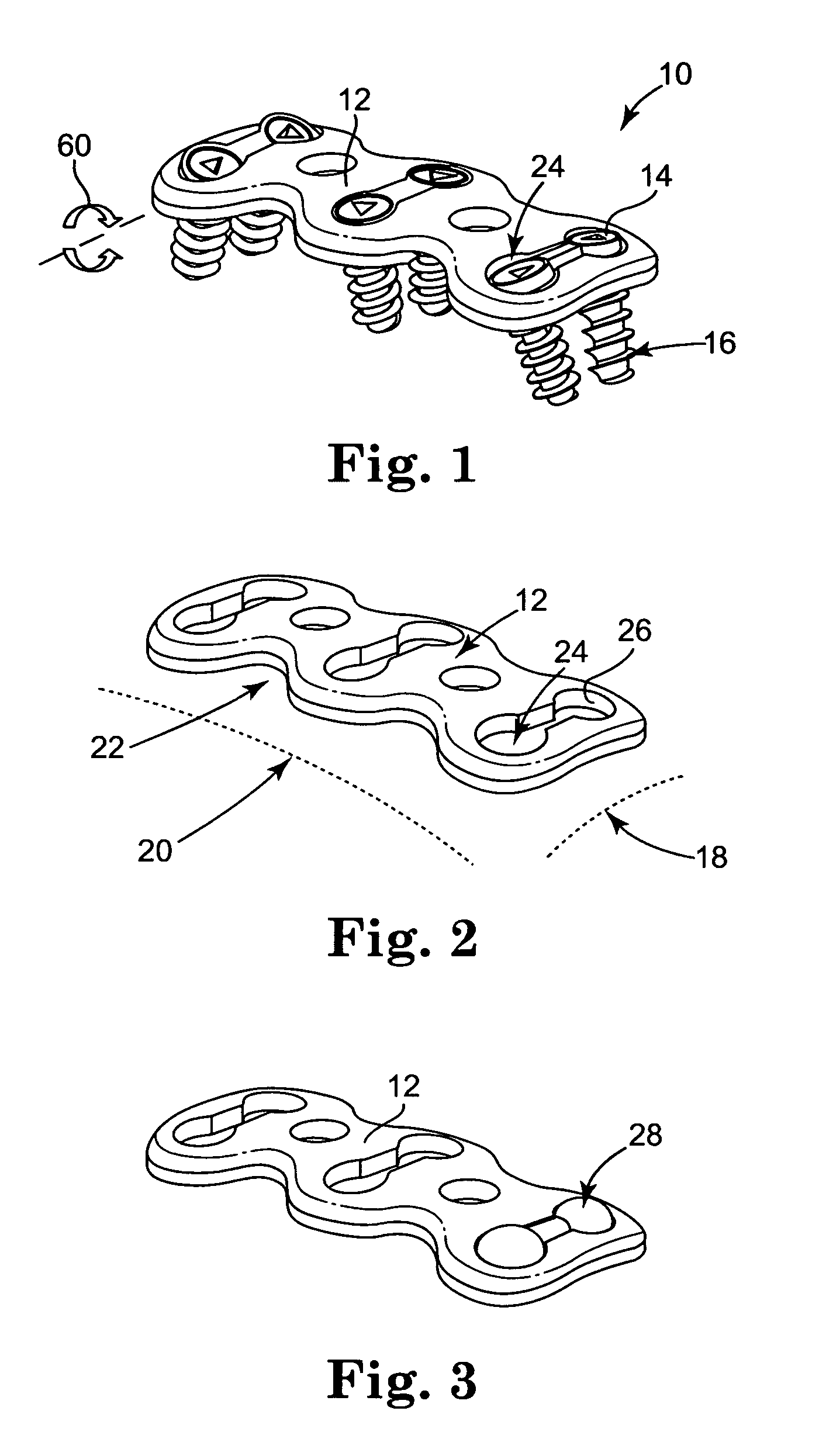
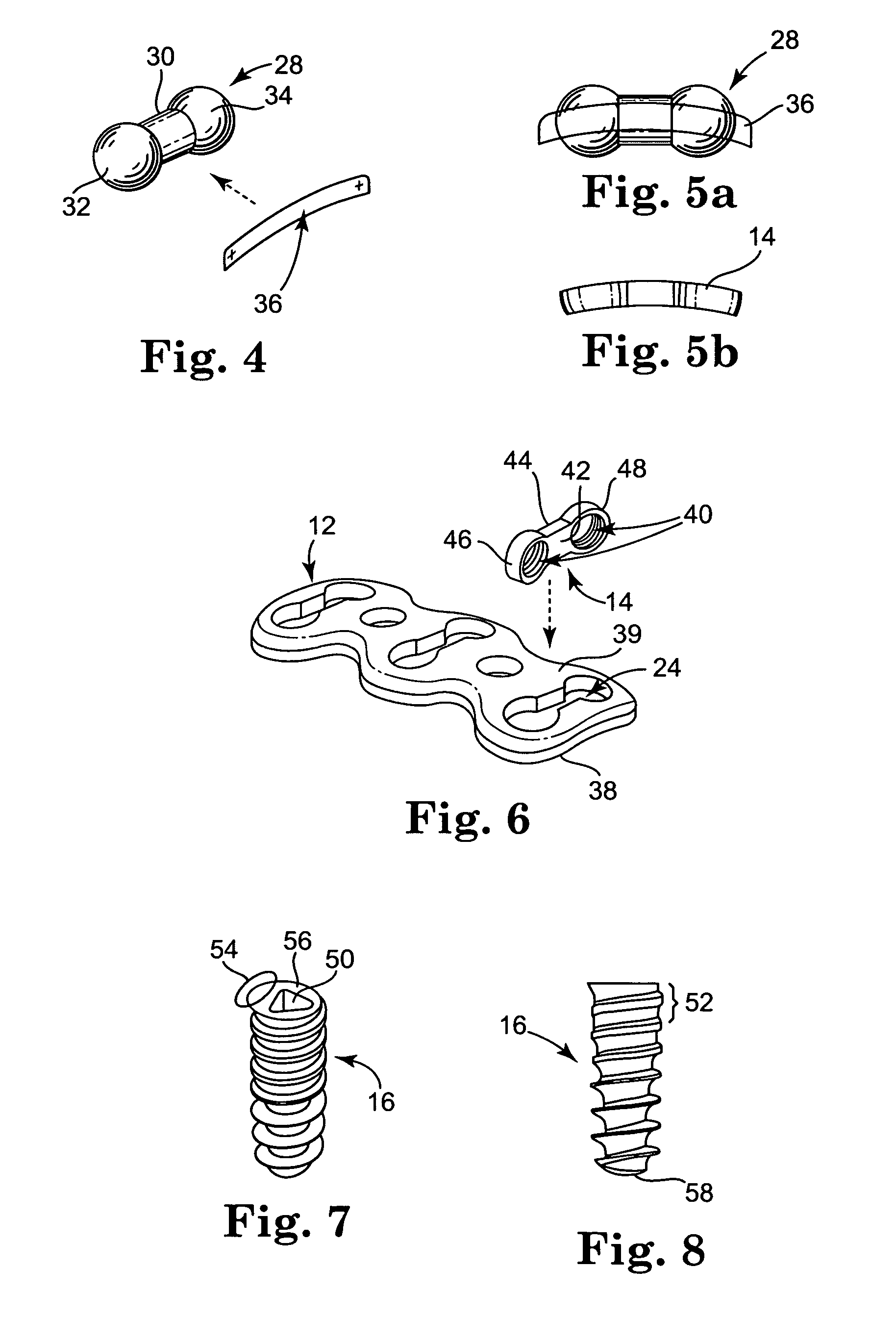
[0025]Referring now to the Figures, wherein the components are labeled with like numerals throughout the several Figures, and initially to FIGS. 1-3, one preferred configuration of a cervical plate system 10 is illustrated. System 10 generally includes a cervical plate 12, at least one rotating element 14, and one or more bone screws 16 for each corresponding rotating element 14. Cervical plate 12 includes a first curvature 18 that is designed to closely match the curvature of the vertebrae in the cervical spine and a second curvature 20 that is designed to closely match the lordotic curvature of the cervical spine. The cervical plate 12 is generally rectangular, and is provided with generally smooth and / or curved edges to minimize discomfort and injury to the patient that might occur with sharp or rough edges. However, the periphery of the plate may have a different general shape, such as oval or elliptical, or may have a more irregular shape. In any case, the cervical plate prefer...


PUM

PropertyMeasurementUnit
diameteraaaaaaaaaa
widthaaaaaaaaaa
lengthaaaaaaaaaa

Abstract

A cervical plate system which includes a cervical plate having a thickness between a top surface and an opposite bottom surface, and at least one slot extending through the thickness of the plate. The system further includes a first rotating element positionable within a first slot of the cervical plate, the first rotating element including at least one threaded hole, and at least one bone screw insertable into the at least one threaded hole of the first rotating element.

Description

TECHNICAL FIELD[0001]The present invention relates to spinal plates for surgical implantation in a patient. The invention more particularly relates to a cervical plate system for fixation of the cervical spine, where such cervical plate system is configured to prevent certain movement of the securing screws once the system is implanted.BACKGROUND OF THE INVENTION[0002]Anterior cervical plates can be used for fixation of the cervical spine. Some of the first anterior cervical plate systems used simple plates and screws, such as the Caspar plate system commercially available from Aesculap Inc., of Center Valley, Pa. However, these plates did not have any mechanism for locking the bone screws to the plate, which thereby created a potential situation where one or more of the screws connecting the plate to the spine could back out of its opening in the spine. These systems have subsequently been modified and now most anterior cervical plating systems available in the market employ some k...

Claims


Application Information

Patent Timeline
Patent Type & Authority Patents(United States)
IPC IPC(8): A61B17/56A61B17/58A61B17/80A61F2/30
CPCA61B17/1655A61B17/1671A61B17/1728A61B17/7059A61B17/8047A61B17/1757Y10T29/49826A61B17/861A61B17/68A61B17/70A61B17/80A61B17/86
Inventor SASING, JUDE L.
Owner GUSTILO RAMON B M D
Why Eureka
Try Eureka