
Mount having structure wherein coupling means is covered, and locking device for means of transportation using same

a technology of coupling means and mounting brackets, which is applied in the direction of anti-theft cycle devices, cycle stands, instruments, etc., can solve the problems of weak spokes being damaged, difficult to prevent, and thefts not being reduced, so as to reduce financial burden, improve security, and facilitate the effect of locking

Active Publication Date: 2020-06-02
HAPPY & GOOD CORP
View PDF13 Cites 0 Cited by
  • Summary
  • Abstract
  • Description
  • Claims
  • Application Information

AI Technical Summary

Benefits of technology

The present invention provides a locking device for bicycles that is secure, easily used, and reduces the need for expensive and inconvenient locks. The device can be easily mounted on any bicycle and used without the need for a key. The invention also includes an RFID tag for identifying bicycle users and solving the issue of bicycles being left unattended. Additionally, the invention enables efficient charging of bicycle batteries and provides real-time tracking and positioning of bicycles using wireless technology.

Problems solved by technology

However, thefts are not still reduced because of thieves aiming for structural weak points.
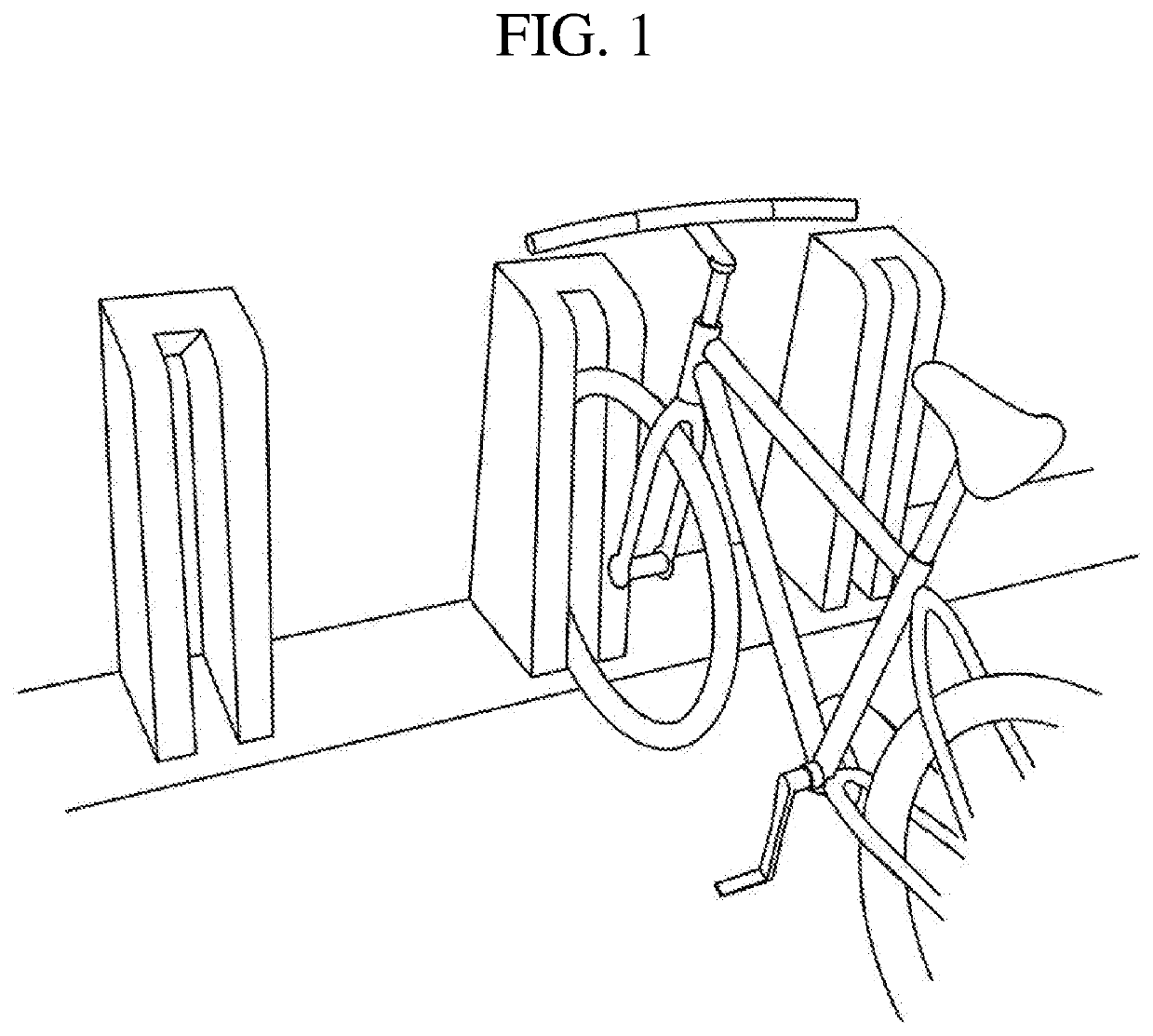
As illustrated in FIG. 1, a conventional locking device configured to constrain wheels is problematic in that it is difficult to prevent the commission of thefts for wheels other than the constrained wheel, and a weak spoke may be damaged, namely, bent or broken by impact applied while the bicycle is stored.
However, since all bicycles should have mounts at uniform heights and positions to facilitate a coupling operation, this locking device may be applied to public bicycles having uniform sizes and shapes, but may not used for private bicycles having various sizes and shapes.

Method used


Image

  • Mount having structure wherein coupling means is covered, and locking device for means of transportation using same
  • Mount having structure wherein coupling means is covered, and locking device for means of transportation using same
  • Mount having structure wherein coupling means is covered, and locking device for means of transportation using same

Examples


Embodiment Construction

[0031]Exemplary embodiments of the present invention will be described below in more detail with reference to the accompanying drawings.

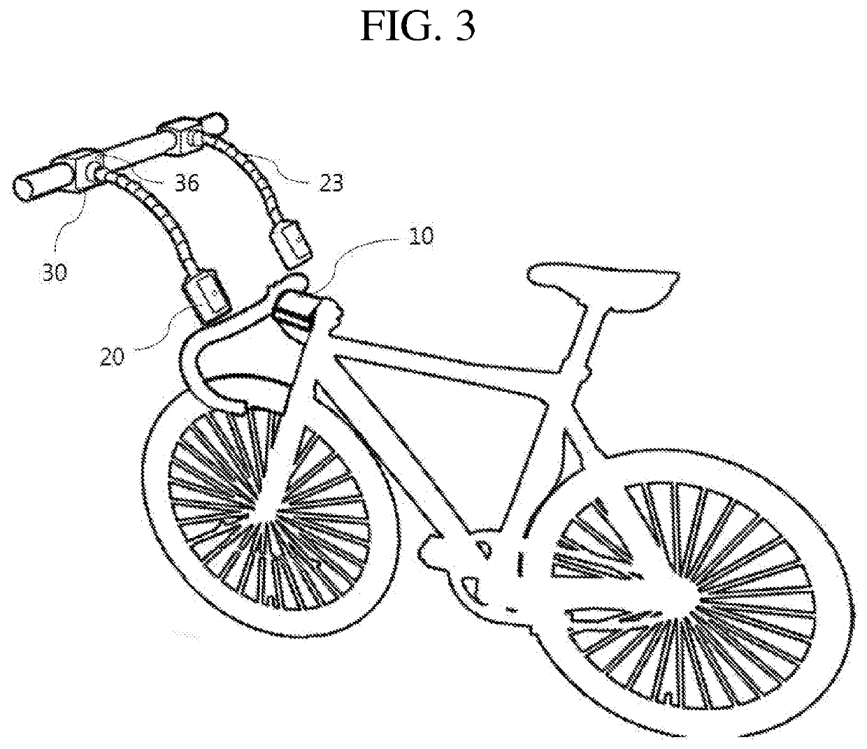
[0032]FIG. 3 is a view illustrating a locking device of a bicycle that is a representative transportation means according to a first embodiment of the present invention. As illustrated in FIGS. 4 and 5 in detail, a coupling structure of a mount 10 mounted on the bicycle includes a body 11, a band 12, and a hook 13. A plurality of catching grooves 12a is formed on the band 12 and at least one catching step is formed on the hook 13 so that the catching grooves engage with the catching step in a saw-tooth manner. Once the catching groove 12a of the band is fitted into the catching step of the hook in a cable-tie coupling manner, this coupling structure makes it impossible to separate the catching step from the catching groove in an opposite direction unless a cutting operation is performed. After a tubular bicycle frame is fitted into an open seam of t...


PUM


Abstract

The present invention relates to a locking device, which is capable of directly locking the body of a means of transportation, such as a bicycle or a light electric vehicle (LEV), regardless of the shape or size thereof, and to a locking device for a means of transportation, which is provided with a mount simply and securely mounted on a tubular frame of the means of transportation, wherein a rack is provided with brackets coupled to the mount and provided at one end of articulated cables, which are fixed to a fixture, so that not only is the locking device securely locked simply by coupling the brackets provided on the rack to the mount mounted on a user's means of transportation, even if the user does not carry a separate lock, but a coupling means, which is capable of disassembling the mount, is covered by the coupling with the brackets when the locking device is locked, thereby significantly reducing the risk of theft during parking.

Description

CROSS-REFERENCE TO RELATED APPLICATIONS[0001]This application is the U.S. National Stage of International Patent Application No. PCT / KR2016 / 005456 filed on May 23, 2016, which claims the priority to Korean Patent Application No. 10-2015-0072189 filed in the Korean Intellectual Property Office on May 22, 2015, the entire contents of which are incorporated herein by reference.TECHNICAL FIELD[0002]The present invention relates to a locking device, which is capable of directly locking a body of a transportation means, such as a bicycle or a light electric vehicle (LEV), regardless of the shape or size thereof. More particularly, the invention relates to a locking device for a transportation means, which is provided with a mount simply and securely mounted on a tubular frame of the transportation means, wherein a rack is provided with brackets coupled to the mount and provided at one end of articulated cables, which are fixed to a fixture, so that not only is the locking device securely ...

Claims


Application Information

Patent Timeline
Patent Type & Authority Patents(United States)
IPC IPC(8): B62H5/00B60L53/31B60L53/12G07C9/28B62H5/20B62H3/00G07C9/00B62H3/02E05B47/00
CPCG07C9/28B60L53/12G07C9/00B60L53/31B62H5/005B62H3/02B62H5/20B62H5/003E05B47/00B62H2003/005B60L2200/12Y02T10/70Y02T10/7072Y02T90/12Y02T90/14
Inventor BYUN, JONG SUB
Owner HAPPY & GOOD CORP
Learn More