Cervical plate system having an insertable rotating element

Active Publication Date: 2008-01-31
GUSTILO RAMON B M D +1
View PDF21 Cites 43 Cited by
  • Summary
  • Abstract
  • Description
  • Claims
  • Application Information

AI Technical Summary

Benefits of technology

[0006]Unlike some of the prior art cervical plate systems, the current invention does not involve a locking element that needs to be engaged after a bone screw is inserted in order to keep the bone screw from backing out of the cervical plate. Instead, the surgical procedure is simplified and involves less components, since screw locking is automatically achieved once the screw is fully inserted and tightened. Also, the systems of this invention do not involve tiny component

Problems solved by technology

However, this same rotating element is not removable from the slot when it is oriented or rotated in a

Method used


Image

  • Cervical plate system having an insertable rotating element
  • Cervical plate system having an insertable rotating element
  • Cervical plate system having an insertable rotating element

Examples


Embodiment Construction

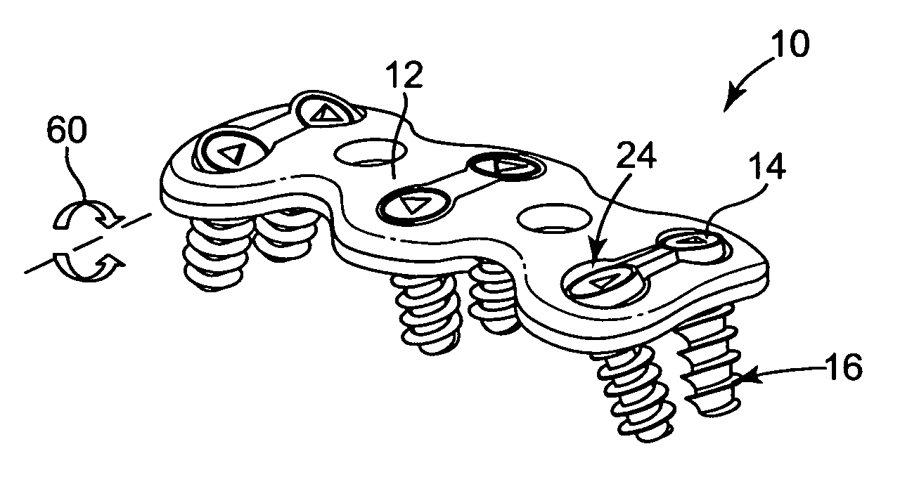
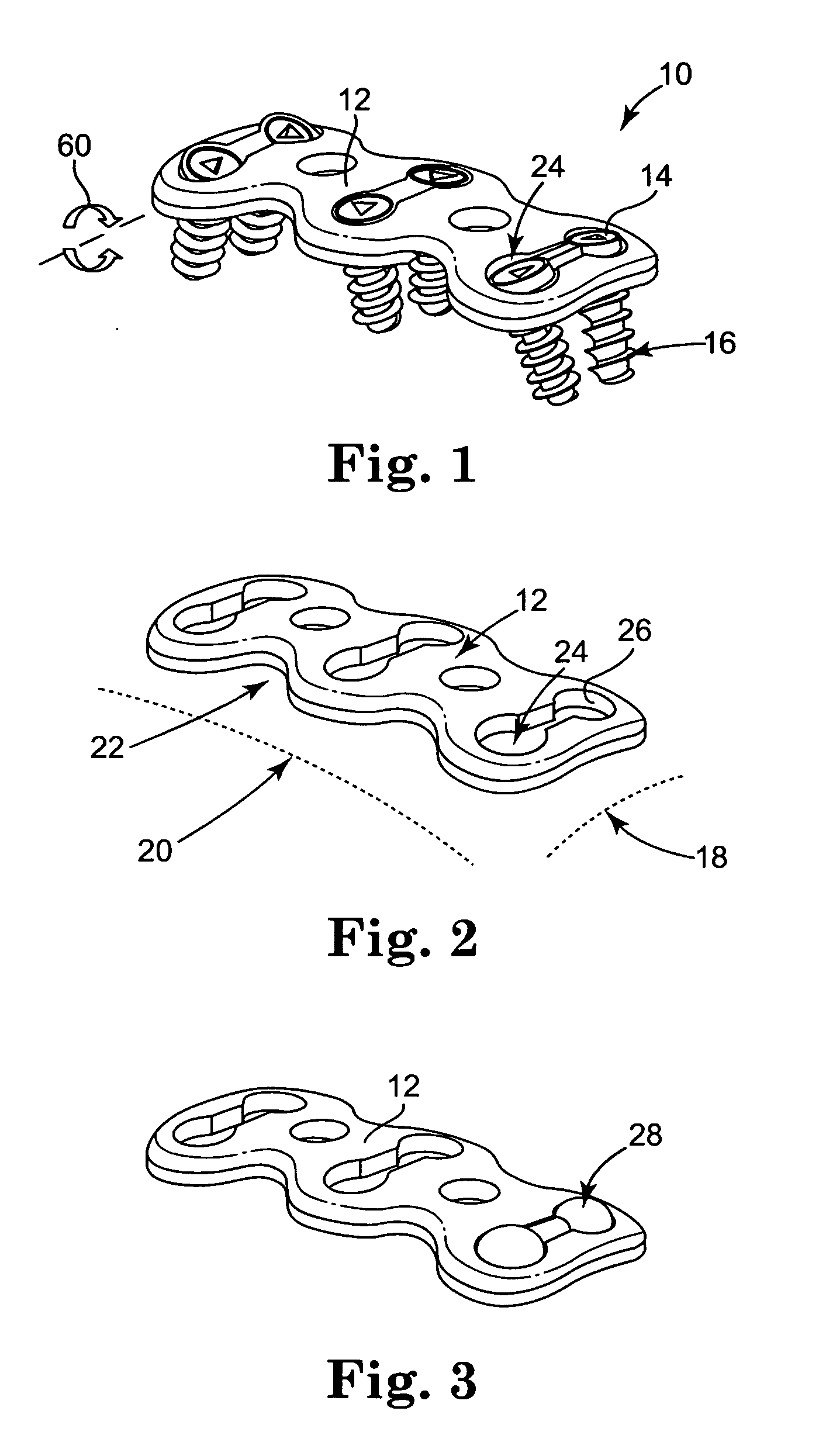
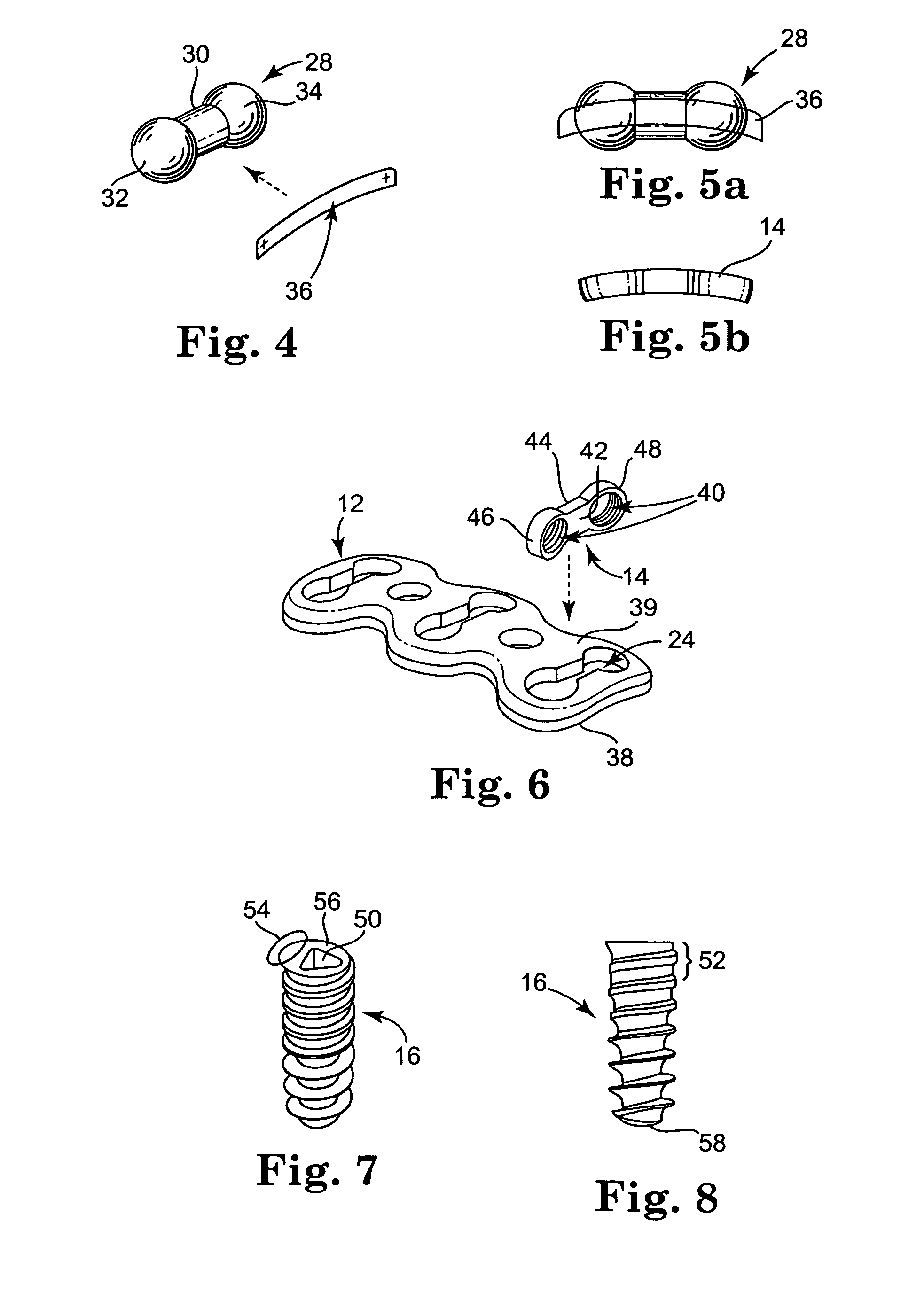
[0025]Referring now to the Figures, wherein the components are labeled with like numerals throughout the several Figures, and initially to FIGS. 1-3, one preferred configuration of a cervical plate system 10 is illustrated. System 10 generally includes a cervical plate 12, at least one rotating element 14, and one or more bone screws 16 for each corresponding rotating element 14. Cervical plate 12 includes a first curvature 18 that is designed to closely match the curvature of the vertebrae in the cervical spine and a second curvature 20 that is designed to closely match the lordotic curvature of the cervical spine. The cervical plate 12 is generally rectangular, and is provided with generally smooth and / or curved edges to minimize discomfort and injury to the patient that might occur with sharp or rough edges. However, the periphery of the plate may have a different general shape, such as oval or elliptical, or may have a more irregular shape. In any case, the cervical plate prefer...


PUM

PropertyMeasurementUnit
Lengthaaaaaaaaaa
Thicknessaaaaaaaaaa
Diameteraaaaaaaaaa

Abstract

A cervical plate system which includes a cervical plate having a thickness between a top surface and an opposite bottom surface, and at least one slot extending through the thickness of the plate. The system further includes a first rotating element positionable within a first slot of the cervical plate, the first rotating element including at least one threaded hole, and at least one bone screw insertable into the at least one threaded hole of the first rotating element.

Description

TECHNICAL FIELD [0001]The present invention relates to spinal plates for surgical implantation in a patient. The invention more particularly relates to a cervical plate system for fixation of the cervical spine, where such cervical plate system is configured to prevent certain movement of the securing screws once the system is implanted.BACKGROUND OF THE INVENTION [0002]Anterior cervical plates can be used for fixation of the cervical spine. Some of the first anterior cervical plate systems used simple plates and screws, such as the Caspar plate system commercially available from Aesculap Inc., of Center Valley, Pa. However, these plates did not have any mechanism for locking the bone screws to the plate, which thereby created a potential situation where one or more of the screws connecting the plate to the spine could back out of its opening in the spine. These systems have subsequently been modified and now most anterior cervical plating systems available in the market employ some...

Claims


Application Information

Patent Timeline
IPC IPC(8): A61F2/30
CPCA61B17/1655A61B17/1671A61B17/1728Y10T29/49826A61B17/7059A61B17/8047A61B17/861A61B17/1757A61B17/68A61B17/70A61B17/80A61B17/86
Inventor SASING, JUDE L.
Owner GUSTILO RAMON B M D
Why Eureka
Try Eureka