LED tube structure capable of changing illumination direction

a technology of led tubes and illumination directions, applied in semiconductor devices, lighting and heating apparatus, light source devices, etc., can solve the problems of mercury pollution, less stable frequency of emitted light, adverse effect on eye health,

Inactive Publication Date: 2012-05-15
YEN HSU LI
View PDF4 Cites 55 Cited by
  • Summary
  • Abstract
  • Description
  • Claims
  • Application Information

AI Technical Summary

Benefits of technology

[0008]The present invention relates to an improved LED tube structure capable of changing an illumination direction, which LED tube structure allows for use of a conventional fluorescent lamp holder and is capable of changing an illumination direction. The LED tube structure mainly comprises: a transparent tube having a corresponding plug track disposed on an inner tube wall thereof, wherein the plug track is disposed on the inner wall of the transparent tube at a height that is approximate to or above a horizontal center line of the transparent tube, and the plug track is adapted for an LED lamp strip to be plugged therein; a conductive terminal being formed of a metal through stamping and having a tandem piece between two terminals thereof; and a positioning enclosure having two terminal plugholes spaced apart disposed in the middle portion thereof for the terminals to be fixedly plugged therein, wherein an inner surface of the positioning enclosure is formed with a circular groove and plug track grooves corresponding to the tube wall and the plug track of the transparent tube, and the plug track grooves are disposed at different angles for the plug track on the inner wall of the transparent tube to be selectively plugged therein, thereby achieving the objective of changing the illumination direction of the LED lamp strip of the LED tube.

Problems solved by technology

The fluorescent lamp can emit bright light, but the frequency of the emitted light is less stable, which may have an adverse influence on eyesight health.
Moreover, a problem of mercury pollution will occur when fluorescent lamps are manufactured and recycled.

Method used


Image

  • LED tube structure capable of changing illumination direction
  • LED tube structure capable of changing illumination direction
  • LED tube structure capable of changing illumination direction

Examples


Embodiment Construction

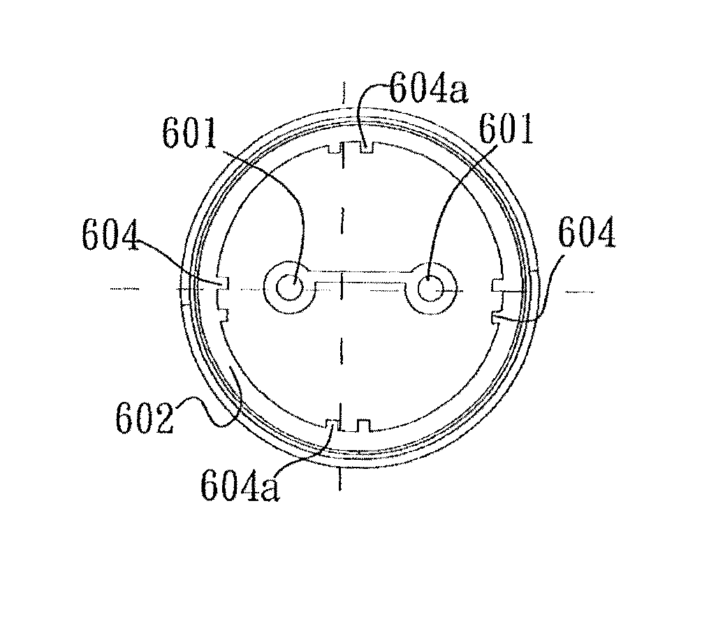
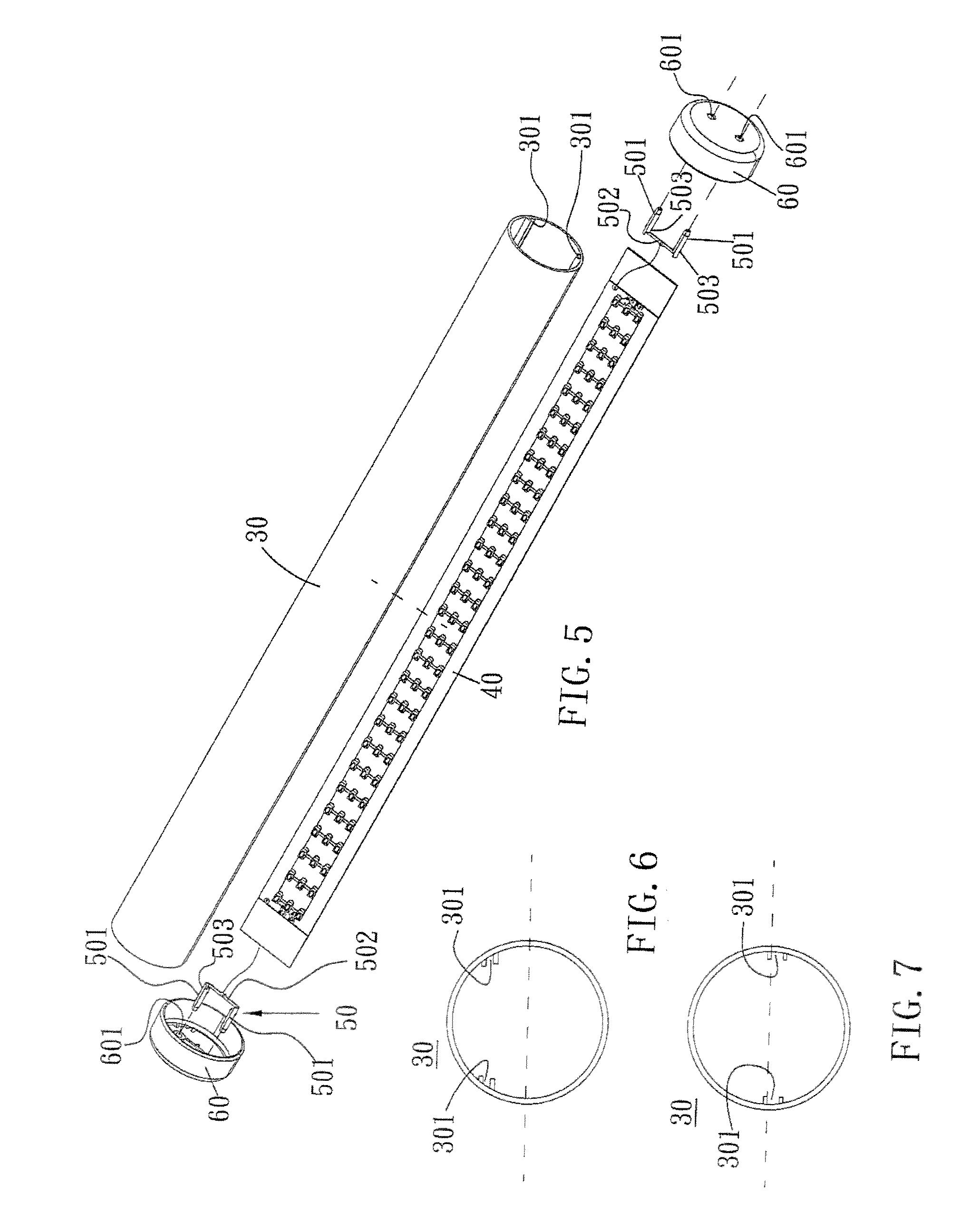
[0022]FIG. 5 is a perspective assembly drawing showing an improved LED tube structure capable of changing an illumination direction according to the present invention. As shown in FIG. 5 (reference may also be made to FIG. 8), the LED tube structure comprises: a transparent tube 30 having a corresponding plug track 301 disposed on an inner tube wall thereof, wherein the plug track 301 is disposed on the inner wall of the transparent tube 30 at a height that is approximate to a horizontal center line (as shown in FIG. 6) of the transparent tube 30 or above the horizontal center line (as shown in FIG. 7), and the plug track 301 is adapted for an LED lamp strip 40 to be plugged and positioned therein; a conductive terminal 501 being formed of a metal through stamping and having a tandem piece 502 between two terminals 501 thereof, wherein both the terminals 501 are provided with a plurality of protruding hooks 503; and a positioning enclosure 60 (as shown in FIG. 9), having two termina...


PUM


Abstract

An improved LED tube structure capable of changing an illumination direction allows for use of a conventional fluorescent lamp holder and is capable of changing an illumination direction. The LED tube structure includes a transparent tube having a plug track disposed on an inner tube wall thereof, wherein the plug track is disposed approximate to or above a horizontal center line of the transparent tube, and the plug track is adapted for an LED lamp strip to be plugged therein; a conductive terminal having a tandem piece between two terminals thereof; and a positioning enclosure having two terminal plugholes spaced apart disposed in the middle portion thereof for the terminals to be fixedly plugged therein. The plug track grooves are disposed at different angles for the plug track on the inner wall of the transparent tube to be selectively plugged therein.

Description

BACKGROUND OF THE INVENTION[0001]1. Technical Field[0002]The present invention relates to an improved LED tube structure capable of changing an illumination direction, which is for use in a lamp.[0003]2. Description of Related Art[0004]Nowadays, various lamps are used for illumination in the life space, and the lamps can be disposed at required positions of the space to change brightness of the space by means of light emitted therefrom, thereby to ensure good lighting conditions. Generally, tubular fluorescent lamps are most commonly used. The fluorescent lamp can emit bright light, but the frequency of the emitted light is less stable, which may have an adverse influence on eyesight health. Moreover, a problem of mercury pollution will occur when fluorescent lamps are manufactured and recycled.[0005]As people's awareness of environmental protection is enhanced, conventional lamp bodies are gradually replaced with current LED tubes all over the world. The LED tubes completely obviat...

Claims


Application Information

Patent Timeline
Patent Type & Authority Patents(United States)
IPC IPC(8): F21S4/00
CPCF21K9/17F21V19/003F21V19/02F21V3/02F21Y2101/02F21K9/27F21Y2115/10F21K9/66
Inventor YEN, HSU LI
Owner YEN HSU LI
Why Eureka
Try Eureka