Fluid Inlet Device, Use, and Method or Retrofitting

a technology of inlet device and flue gas, which is applied in the direction of vacuum distillation separation, liquid degasification, separation process, etc., can solve the problems of reducing the overall separation efficiency of the inlet device, re-entrainment, and complexity. and performan

Active Publication Date: 2008-11-27
SHELL OIL CO
View PDF13 Cites 21 Cited by
  • Summary
  • Abstract
  • Description
  • Claims
  • Application Information

AI Technical Summary

Benefits of technology

[0040]Suitably also, the liquid catcher channel has a downstream end that extends until the downstream end of the trailing end of the guide member, or beyond the trailing end. By extending the liquid catcher channel beyond the guide member, the liquid can be guided into an area where the gas velocities are much smaller. The downstream part of the liquid catcher channel can also be arranged to alter the direction of liquid release into the vessel. For example, when the main flow direction in the fluid inlet device is horizontal, the downstream part can be directed downwards, albeit suitably not abruptly.
[0041]The channel can in particular be formed by an angled profile, e.g. of an inverted L, V or U shape. Another possibility is that the channel has the shape of a tubular section, which is a tubular of which a longitudinal part has been cut out along its length.
[0042]The fluid inlet device in accordance with the invention can be used as fluid inlet device into a gas-liquid contacting vessel, in particular into a distillation column, more in particular a high-vacuum distillation column, or into a separation vessel.

Problems solved by technology

There are different types of inlet devices, varying in complexity and performance.
Re-entrainment lowers the overall separation efficiency of the inlet device, since liquid that was already separated on the concave side of the vane, and that should ideally find its way towards the bottom of the vessel, is still carried upwardly with the gas.

Method used


Image

  • Fluid Inlet Device, Use, and Method or Retrofitting
  • Fluid Inlet Device, Use, and Method or Retrofitting
  • Fluid Inlet Device, Use, and Method or Retrofitting

Examples


example

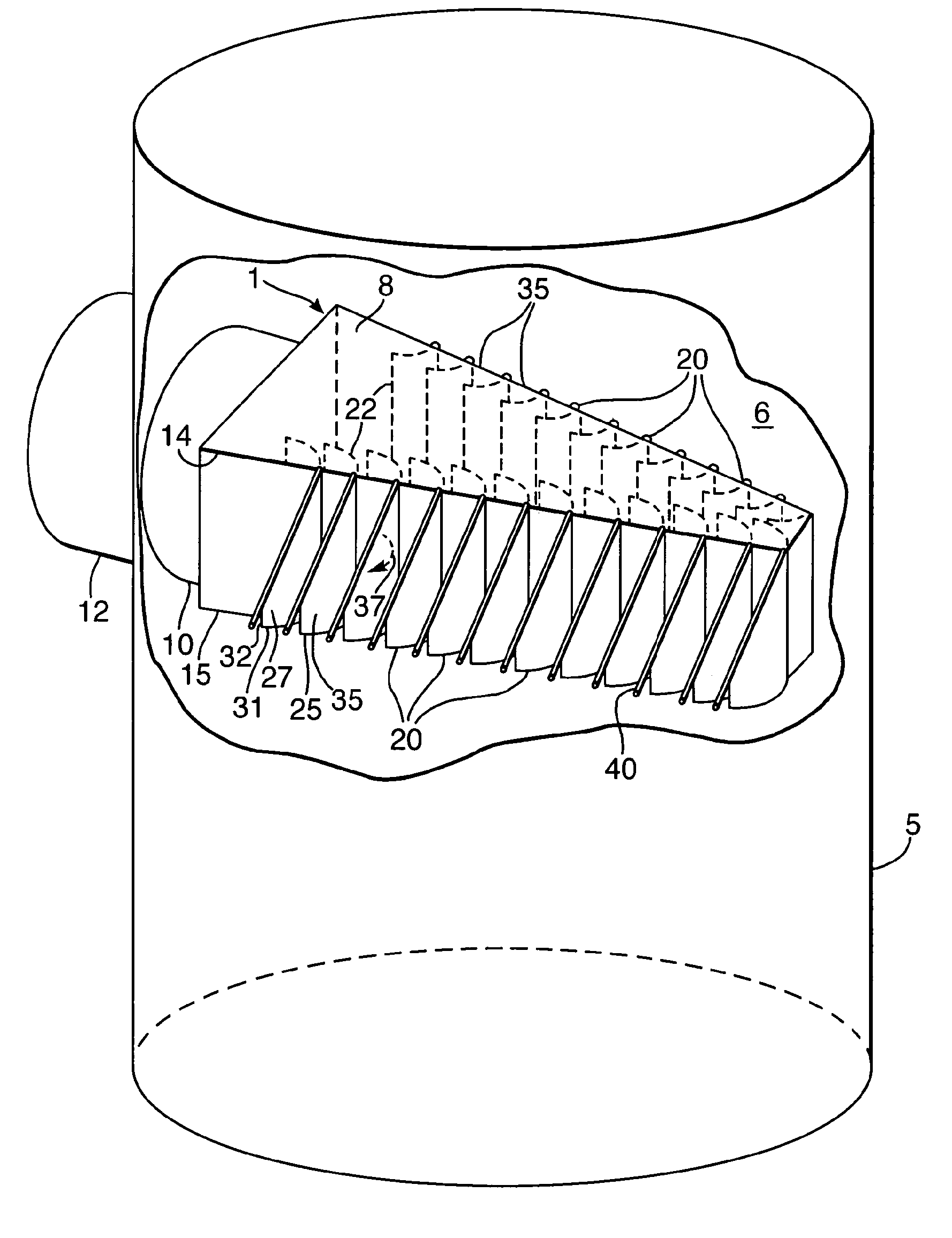
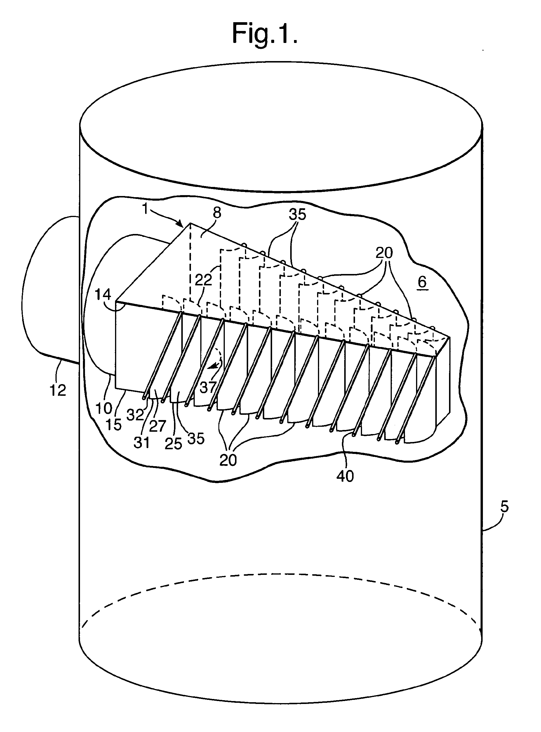
[0135]A fluid inlet device generally according to FIG. 1 was tested before and after retrofitting with liquid catcher channels in accordance with the invention. The fluid inlet device was horizontally mounted in a column of 1 m diameter, generally as shown in FIG. 1, but in a dual ladder configuration with 28 vanes in total, 14 vanes on either side arranged in two stacked rows of 7 vanes each. Each vane was 0.144 m high, and the feedpipe to the column inlet had a diameter of 0.28 m.

[0136]The fluid inlet device was tested before mounting of liquid catcher channels. A water / air mixture was fed to the feed pipe in which the water was dispersed in the air as droplets with a size as is typically present in transfer lines to high vacuum units. Tests were conducted over a range of air inlet velocities of 30-60 m / s, and using a water to air mass ratio of 0.3.

[0137]The amount of entrainment in the gas was determined by using a vanepack mounted above the vane inlet device. The water caught in...


PUM

PropertyMeasurementUnit
angleaaaaaaaaaa
angleaaaaaaaaaa
angleaaaaaaaaaa

Abstract

A fluid inlet device (1) suitable for introducing a mixture of liquid and gas into a vessel, which fluid inlet device comprises a guide member having a surface on which surface a liquid film is present during normal operation, and having a main direction of gas flow along the surface; and wherein the guide member (20) is provided with a liquid catcher channel (40) extending from an upstream position with respect to the guide member (20) to a downstream position, and wherein a virtual line along the guide member between the upstream position and the downstream position deviates from the main direction of gas flow; the use of the fluid inlet device for introducing a mixture of liquid and gas into a gas-liquid contacting vessel; and a method of retrofitting a fluid inlet device.

Description

FIELD OF THE INVENTION[0001]The present invention relates to a fluid inlet device suitable for introducing a mixture of liquid and gas into a vessel, to the use of such a device, and to a method of retrofitting a fluid inlet device.BACKGROUND OF THE INVENTION[0002]In many installations in the upstream or downstream oil and gas industry, chemical and petrochemical industry, it is required to introduce a mixture of liquid and gas into a processing vessel. The vessel can be a separation vessel designed to separate the stream, e.g. a natural gas stream comprising oil and / or water, into liquid and gas streams. The vessel can also be a gas / liquid contacting vessel in which gas and liquid are counter-currently contacted to exchange heat or matter. An example of such a gas / liquid contacting vessel is a fractionation or distillation column, and a particular example is a vacuum distillation column.[0003]In the specification and in the claims the word ‘gas’ is used to refer to gas and to vapou...

Claims


Application Information

Patent Timeline
Patent Type & Authority Applications(United States)
IPC IPC(8): C10J1/08
CPCB01D1/305B01D3/00B01D3/008B01D3/10B01D3/26B01D45/08F15D1/0005
Inventor KOOIJMAN, HENDRIK ADRIAANNOOIJEN, JOHANNES LAMBERTUS
Owner SHELL OIL CO
Why Eureka
Try Eureka