Broadcast spreader with a directional control assembly

a technology of directional control and spreader, which is applied in the direction of sowing, agriculture, centrifugal wheel fertilisers, etc., can solve the problems of not being able to meet the needs of all uses and applications, and the amount of granular material to be thrown may be greater or less,

Active Publication Date: 2011-12-13
BRINLY-HARDY COMPANY
View PDF29 Cites 21 Cited by
  • Summary
  • Abstract
  • Description
  • Claims
  • Application Information

AI Technical Summary

Benefits of technology

[0017]Thus, the second plate serves as a shutter to open or close the pathway for the granular material from the hopper through the discharge port and onto the rotating fan. In other words, the sliding movement of the second plate with respect to the hopper and the first plate allows the user to select the flow rate of the granular material by setting the second plate (i.e., the position of the rear opening defined by the second plate relative to the discharge port) in a closed position, a fully open position, or a position therebetween. Then, movement of the first plate relative to the hopper causes a shifting of the pathway for the granular material, thus altering the direction of the distribution pattern. Thus, in operation, the construction of the directional control assembly not only provides for control of the flow of material to the rotating fan (on / off), but also allows for the shifting of the distribution pattern from side to side and ensures a consistent and even distribution pattern.

Problems solved by technology

However, it is recognized that different types of material and / or different speeds of travel have the undesirable effect of skewing the direction and distance the material is thrown to one side or the other, or causing a greater or lesser amount of granular material to be thrown in a certain direction.
However, Applicants have recognized that such a construction may not be optimal for all uses and applications, and that there remains a need for a broadcast spreader that includes a directional control, allowing the operator to adjust the direction of the distribution pattern and ensure a consistent and even distribution pattern.

Method used


Image

  • Broadcast spreader with a directional control assembly
  • Broadcast spreader with a directional control assembly
  • Broadcast spreader with a directional control assembly

Examples


Embodiment Construction

[0031]The present invention is a broadcast spreader with a directional control assembly.

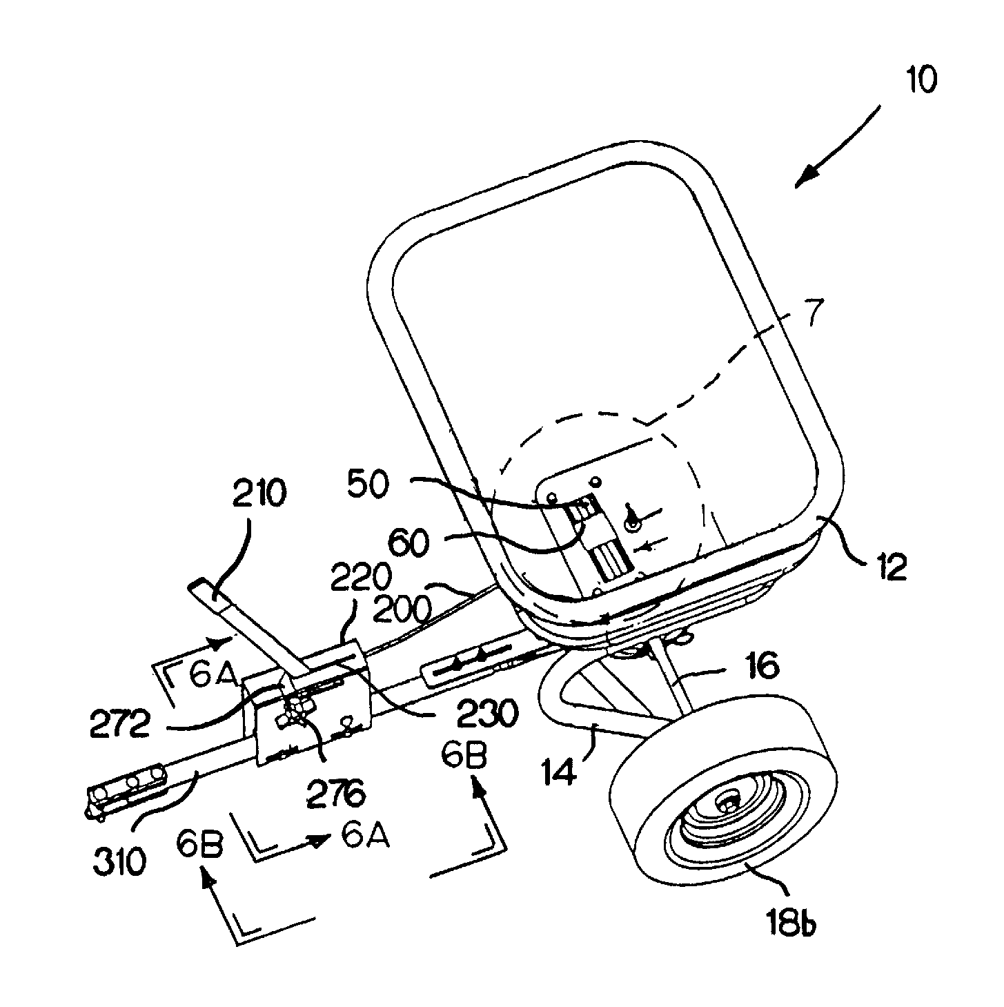
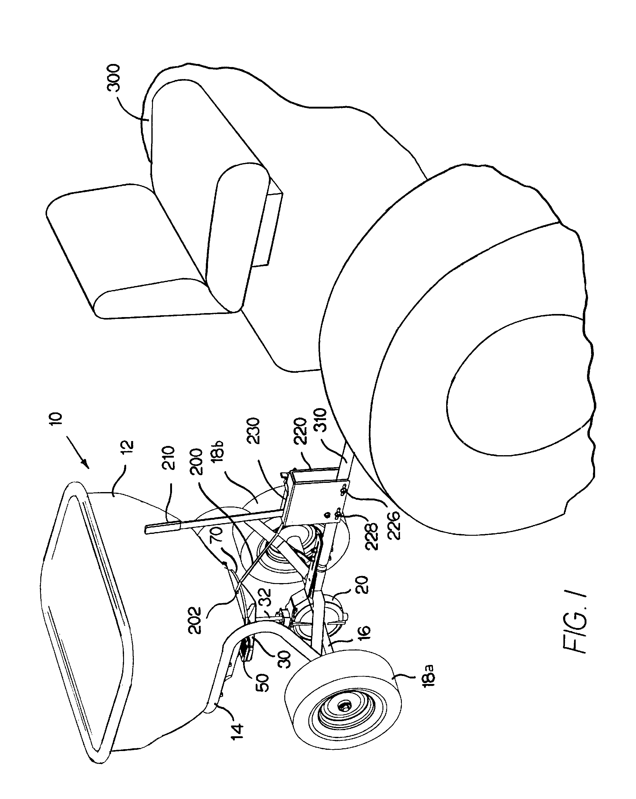
[0032]FIG. 1 is a perspective view of an exemplary broadcast spreader 10 made in accordance with the present invention secured to and being towed behind a tractor 300. The broadcast spreader 10 generally includes a hopper 12 that is mounted on a support frame 14. An axle 16 extends through a lower portion of this support frame 14, with wheels 18a, 18b being mounted on either end of the axle 16. The support frame 14 is connected to a tow bar 310, linking the broadcast spreader 10 to the tractor 300.

[0033]As mentioned above, in alternate embodiments, the hopper may be mounted to a vehicle (such as an all-terrain vehicle) or another engine-driven platform, or the hopper may be mounted on wheels but provided with a handle so that it can be manually pushed.

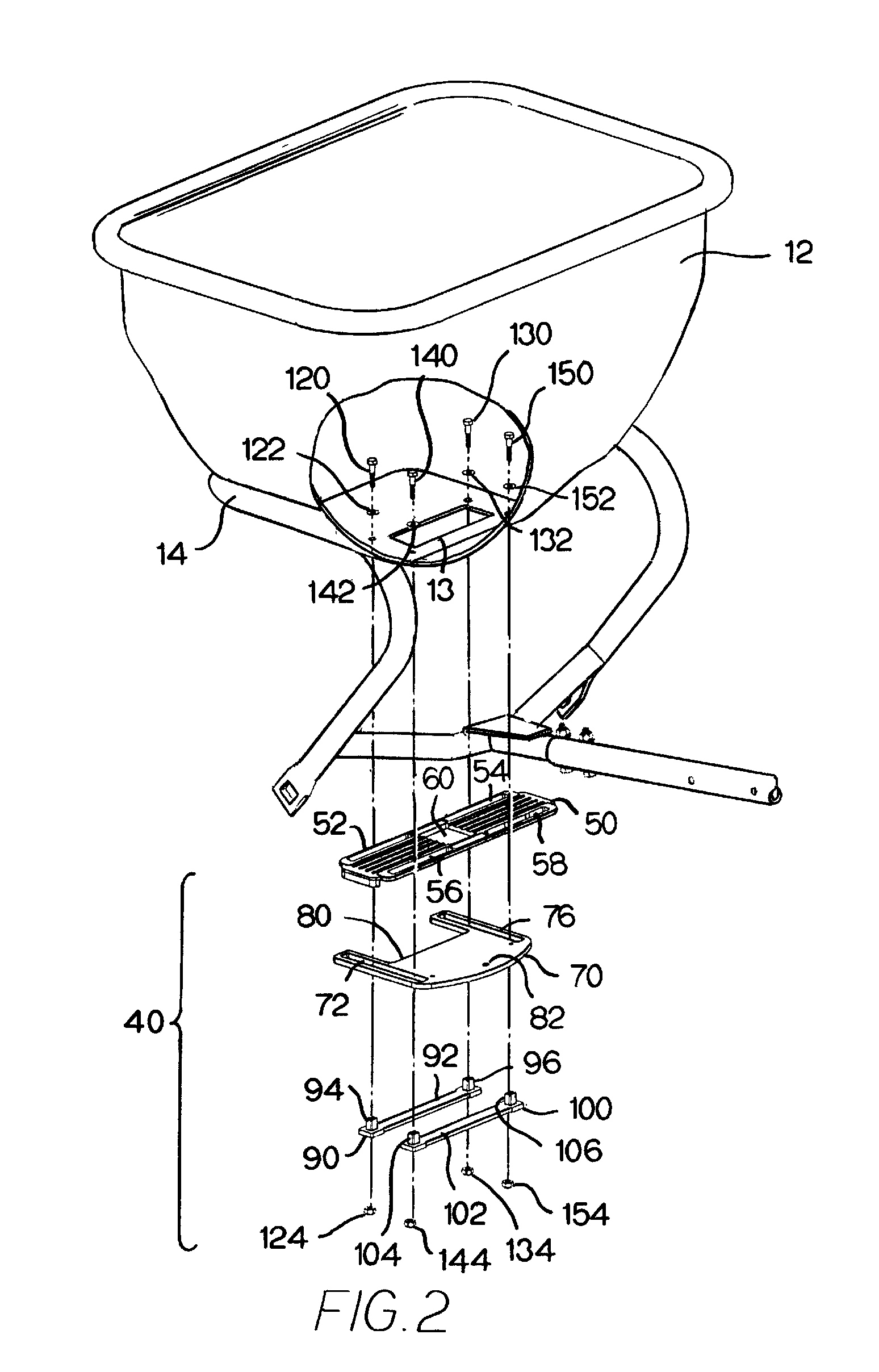
[0034]Referring again to FIG. 1 and the exploded perspective view of FIG. 2, like most broadcast spreaders, the exemplary broadcast spreader 10 inc...


PUM


Abstract

A broadcast spreader includes a directional control assembly that defines a pathway for granular material from a hopper through a discharge port and onto a rotating fan. The directional control assembly includes a first plate that is secured to and adapted for slidable movement with respect to the hopper. The first plate defines an opening therethrough that is substantially in registry with but smaller than the discharge port, thus serving to define a pathway for the granular material from the hopper through the discharge port and onto the fan. The directional control assembly further includes a second plate secured to and adapted for slidable movement with respect to the hopper and the first plate. Movement of the second plate relative to the first plate selectively opens or closes the pathway for the granular material from the hopper through the discharge port and onto the fan.

Description

BACKGROUND OF THE INVENTION[0001]The present invention relates to a broadcast spreader, and, more particularly, to a broadcast spreader with a directional control assembly.[0002]A broadcast spreader (which may also be referred to as a rotary spreader or a spin spreader) is commonly used to distribute granular materials, such as seed, fertilizers, pelletized lime, insecticides, salts, ice melts, and / or mulch to a lawn, field, pasture, paved surface, or other outdoor surface. A broadcast spreader is generally comprised of a hopper mounted on wheels with a means for attaching the broadcast spreader to a tractor, truck, riding mower, or other vehicle. Alternatively, the hopper may be mounted to a vehicle (such as an all-terrain vehicle) or another engine-driven platform, or the hopper may be mounted on wheels but provided with a handle so that it can be manually pushed. Whether towed behind a vehicle, mounted to a vehicle, or pushed, the broadcast spreader distributes granular materials...

Claims


Application Information

Patent Timeline
Patent Type & Authority Patents(United States)
IPC IPC(8): A01C7/02A01C17/00
CPCA01C17/006
Inventor HOBBS, PATRICK
Owner BRINLY-HARDY COMPANY
Why Eureka
Try Eureka