Magnetic fan-attaching structure and magnetic attaching element thereof

a technology of magnetizing fan and attachment structure, which is applied in the direction of electrical apparatus casings/cabinets/drawers, washers, instruments, etc., can solve the problems of large amount of heat generated, damage to electronic components, computer shutdown, etc., and achieve convenient and rapid installation, easy installation or addition of fans

Inactive Publication Date: 2008-09-18
ENERMAX TECHNOLOGY CORPORATION
View PDF1 Cites 20 Cited by
  • Summary
  • Abstract
  • Description
  • Claims
  • Application Information

AI Technical Summary

Benefits of technology

[0007]One particular aspect of the present invention is to provide a magnetic fan-attaching structure. It utilizes a magnetic attaching element to combine a through hole preformed on the fan body to form the magneti

Problems solved by technology

Because a lot of circuit boards and electronic components are located in a computer housing, a large amount of heat is generated by the graphics card, chips, and integrated circuits located on the circuit board in the computer housing when the computer is operating.
If the temperature in the housing exceeds the operating temperature specifications of the electronic components, the electronic components will be damaged and the co

Method used


Image

  • Magnetic fan-attaching structure and magnetic attaching element thereof
  • Magnetic fan-attaching structure and magnetic attaching element thereof
  • Magnetic fan-attaching structure and magnetic attaching element thereof

Examples


Embodiment Construction

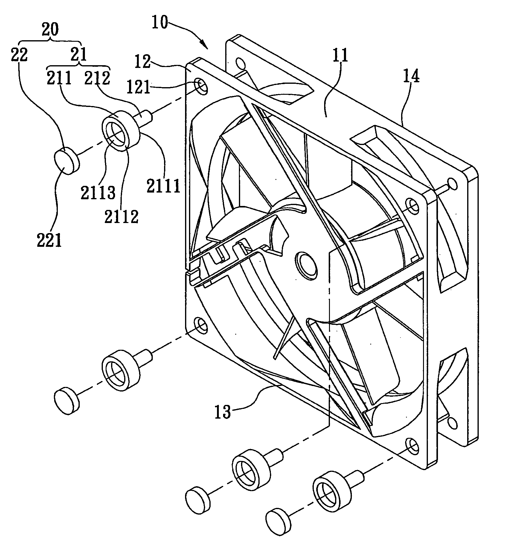
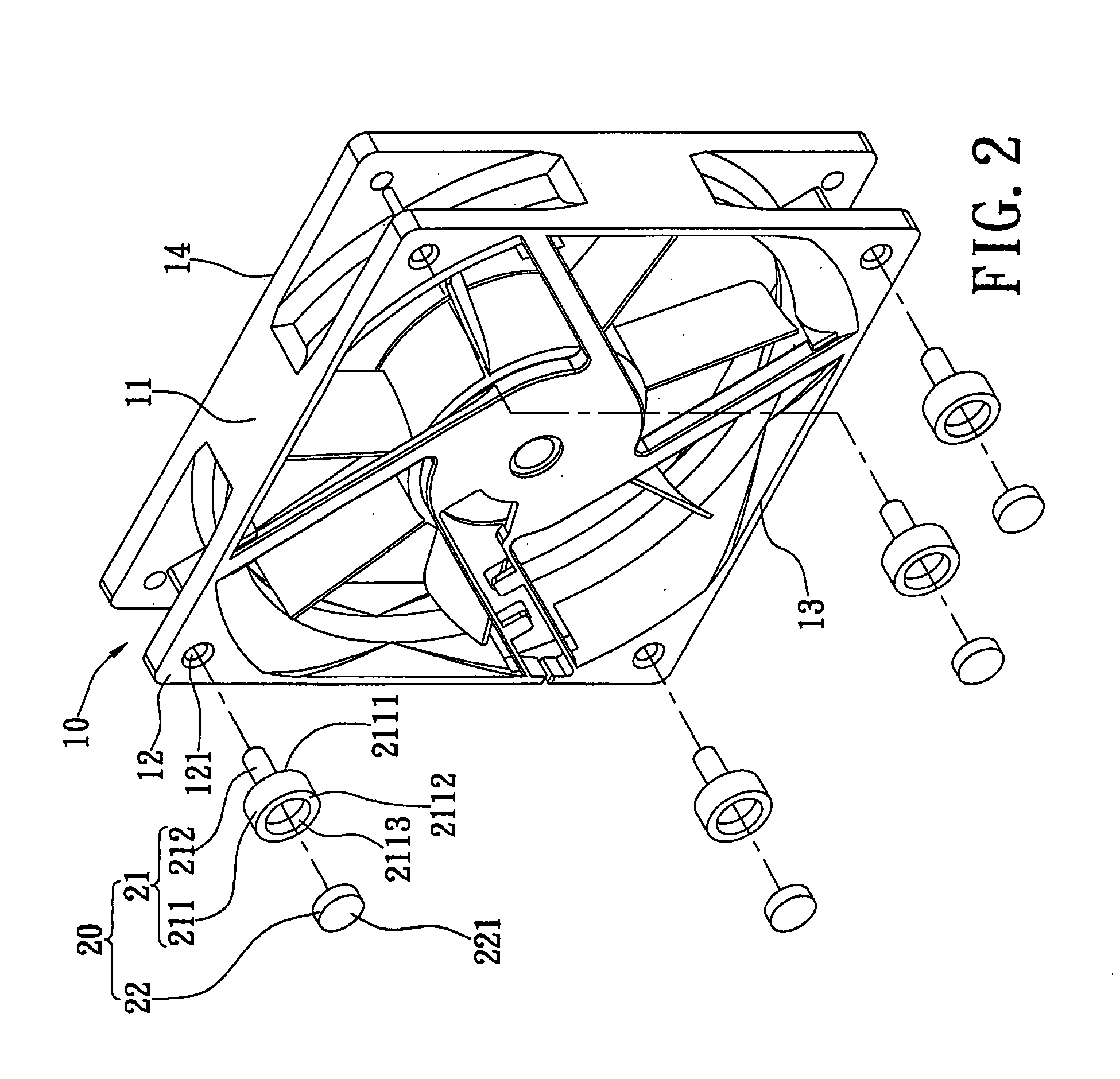
[0022]Reference is made to FIGS. 2 and 3. The magnetic fan-attaching structure includes a fan body 10, and four magnetic attaching elements 20.

[0023]The fan body 10 has a frame body 11. The edges of the front side and the rear side of the frame body 11 extend outwards to form four fastening boards 12. The four fastening boards 12 are located at the four corners of the fan body 10. Each fastening board 12 has a through hole 121. The frame body 11 has a front side surface and a rear side surface that is opposite to each other. The front side surface is an air-exhausting surface 13. The rear side surface is an air-supplying surface 14. The air enters into the fan body 10 via the air-supplying surface 14, and is exhausted to outside of the fan body 10 via the air-exhausting surface 13.

[0024]Each magnetic attaching element 20 includes a main body 21 and a magnetic unit 22. The main body 21 has a head portion 211 and a rod body 212. In this embodiment, the edge of the head portion 211 is ...


PUM


Abstract

A magnetic fan-attaching structure and a magnetic attaching element are disclosed. The magnetic fan-attaching structure includes a fan body and at least one magnetic attaching element. The fan body has at least one through hole. The magnetic attaching element includes a main body and a magnetic unit located at the main body. The main body has a head portion and a rod body. The head portion has a contacting surface and an attaching surface that are opposite to the contacting surface. The contacting surface is linked to the rod body. The attaching surface is exposed to a side surface of the fan body. The rod body passes through the through hole to combine the magnetic attaching element with the fan body. Thereby, the fan body can be easily and rapidly installed at the desired location by a magnetic-absorbing method. It is convenient for users.

Description

BACKGROUND OF THE INVENTION[0001]1. Field of the Invention[0002]The present invention relates to a fan structure. In particular, this invention relates to a magnetic fan-attaching structure in which a magnetic attaching element is installed in the through hole of the fan body.[0003]2. Description of the Related Art[0004]Because a lot of circuit boards and electronic components are located in a computer housing, a large amount of heat is generated by the graphics card, chips, and integrated circuits located on the circuit board in the computer housing when the computer is operating. The temperature inside the computer housing therefore rises. If the temperature in the housing exceeds the operating temperature specifications of the electronic components, the electronic components will be damaged and the computer will shut down. Therefore, cooling holes are formed on the housing and fans are installed in the housing. When the computer is operating, the heat generated from the electroni...

Claims


Application Information

Patent Timeline
IPC IPC(8): H05K5/00F16B19/00F16B33/00
CPCF04D29/601F16B19/00F16B35/00H05K7/20172F16B2001/0035G06F1/183G06F1/20F16B35/06F16B2200/83
Inventor HUNG, CHUNG-LIANG
Owner ENERMAX TECHNOLOGY CORPORATION
Why Eureka
Try Eureka