Method and apparatus for evaluation of coated parts

a coating and apparatus technology, applied in hydrodynamic testing, material strength using steady bending force, instruments, etc., can solve problems such as the possibility of destructive evaluation of parts

Active Publication Date: 2012-05-15
HAMILTON SUNDSTRAND CORP
View PDF16 Cites 9 Cited by
  • Summary
  • Abstract
  • Description
  • Claims
  • Application Information

AI Technical Summary

Problems solved by technology

Potentially destructive evaluation of parts can be done to extract samples from components and running the test.

Method used


Image

  • Method and apparatus for evaluation of coated parts
  • Method and apparatus for evaluation of coated parts
  • Method and apparatus for evaluation of coated parts

Examples


Embodiment Construction

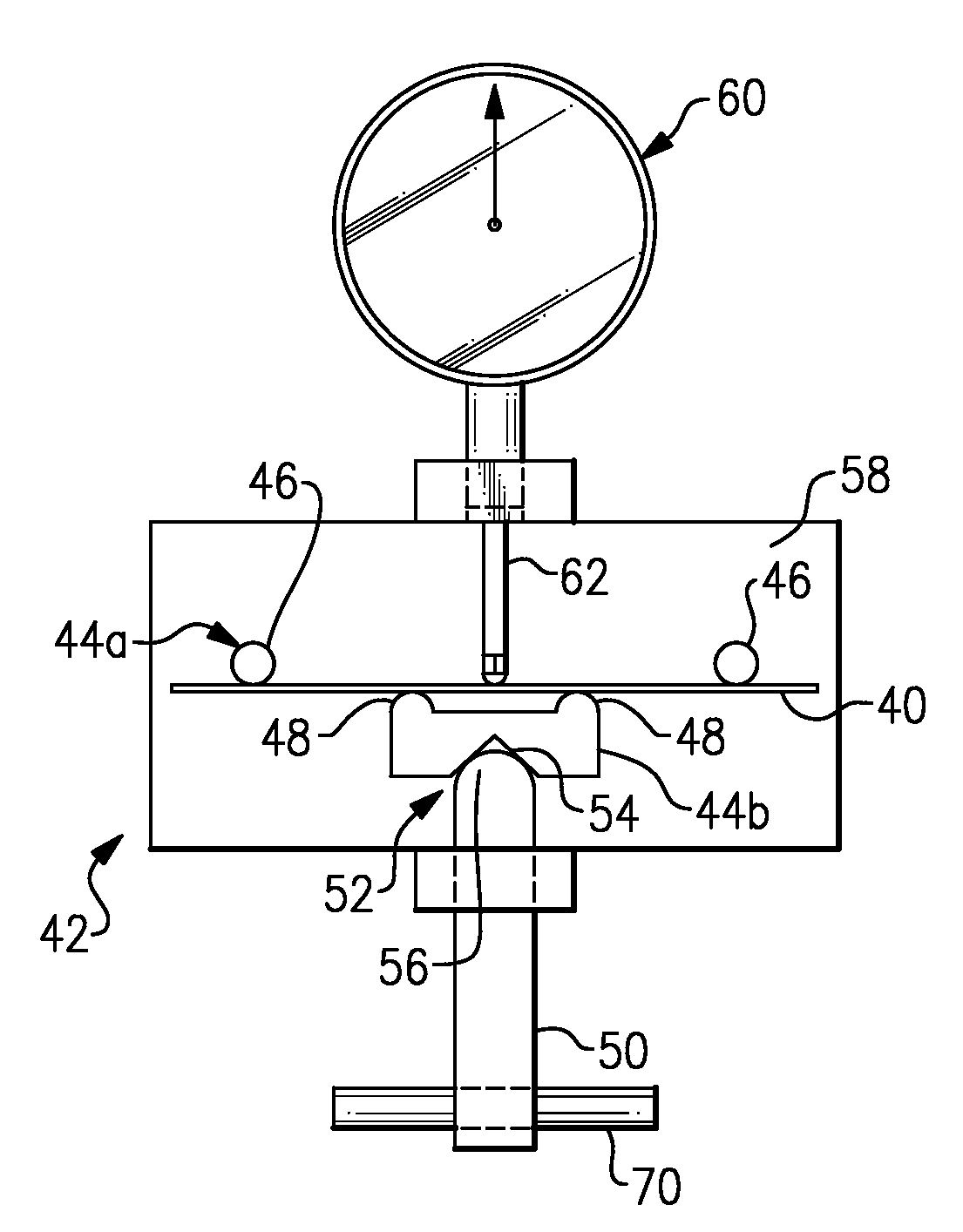
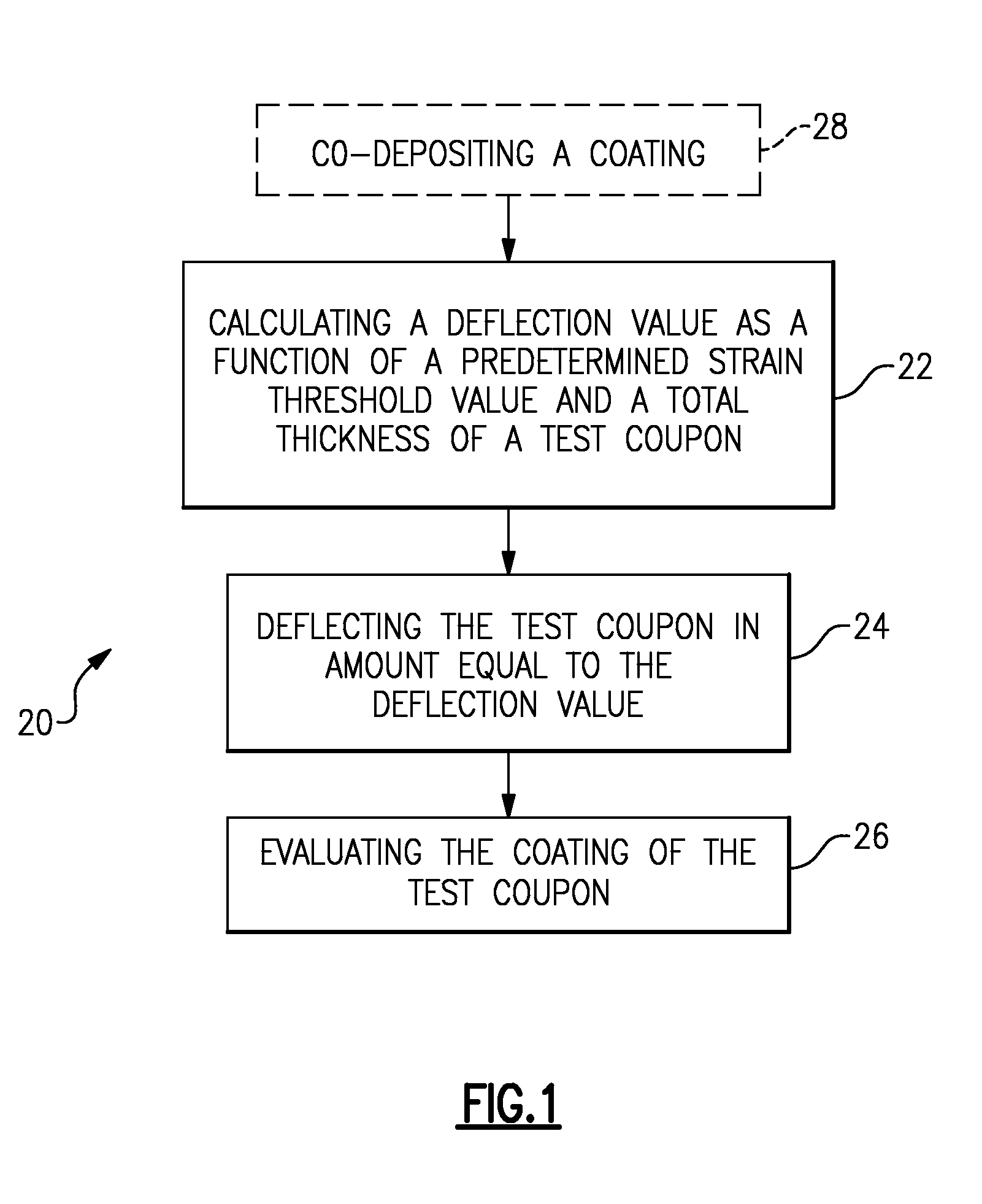
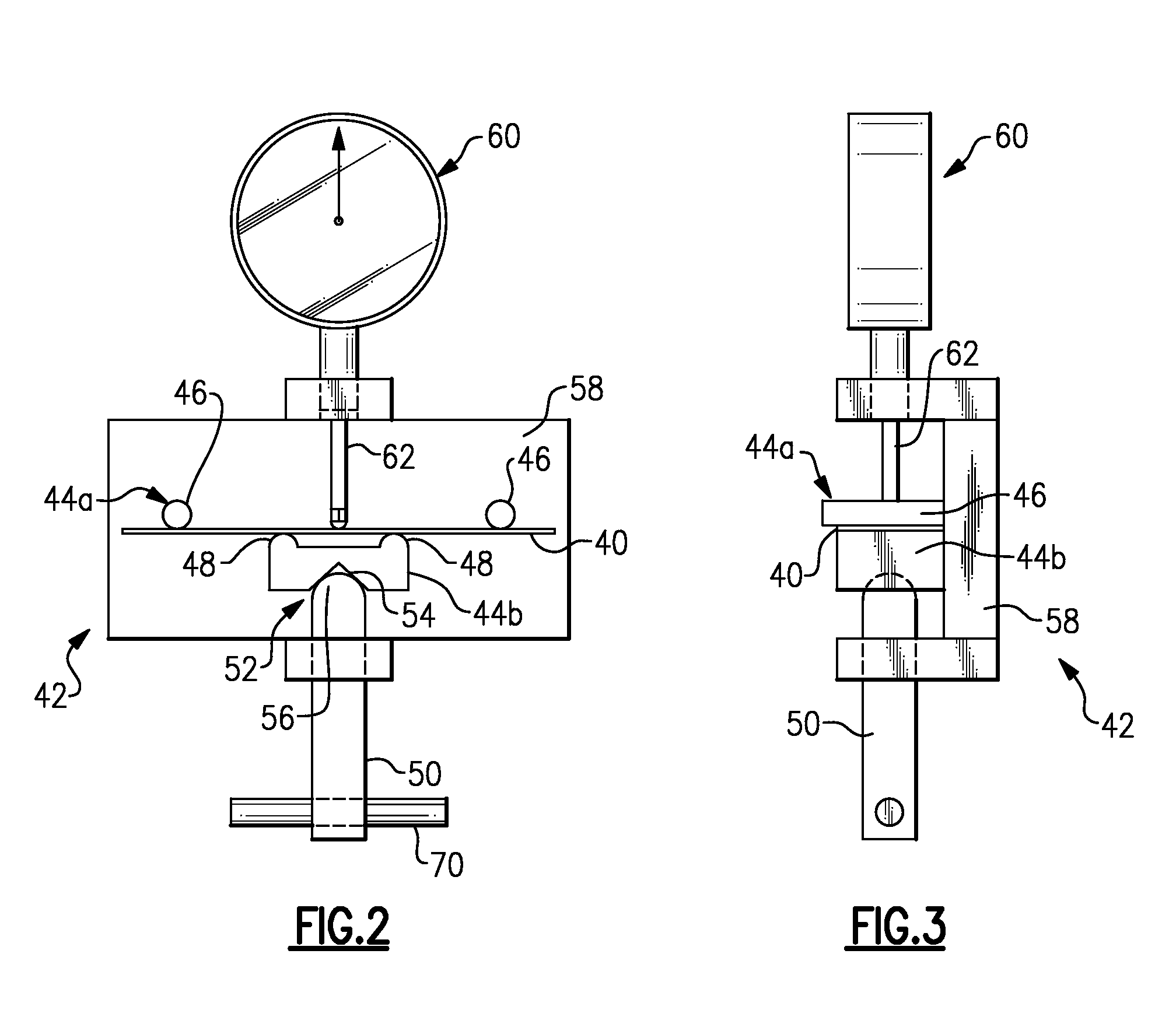
[0012]FIG. 1 illustrates an example method 20 of non-destructively verifying performance of a coating. It is to be understood that the method 20 is not limited to any particular type of coated part and may be applied parts coated using any deposition process, such as electroplating, plasma-spraying, and the like. In particular, the method 20 involves deflecting a test coupon as an indication of whether a mechanical characteristic, such as fatigue performance, of a coated part meets a specified level. Thus, the method 20 avoids destruction of the coated part or parts for evaluation purposes. The method 20 includes a calculation step 22, a deflection step 24, an evaluation step 26 and, optionally, a co-deposition step 28.

[0013]The test coupon may be produced in a co-deposition process such that a substrate of the test coupon and substrate of the part or parts are coated under the same conditions at approximately the same time. The coating of the test coupon is therefore representative...


PUM

PropertyMeasurementUnit
thicknessaaaaaaaaaa
mechanical characteristicaaaaaaaaaa
strain thresholdaaaaaaaaaa

Abstract

A method of verifying performance of a coated part includes calculating a deflection value as a function of a predetermined strain threshold value and a total thickness of a test coupon that comprises a coating on a substrate. The coating of the test coupon is co-deposited in a deposition process for producing a coated part. The test coupon is bent in an amount equal to the calculated deflection value and then evaluated as an indication of whether a mechanical characteristic of the coated part meets a specified level.

Description

BACKGROUND OF THE INVENTION[0001]This disclosure relates to a method and fixture for non-destructively verifying performance of a coated part. Hard coatings are typically applied to external surfaces of parts to enhance wear resistance, erosion resistance, or other properties of the part. The hard coating may debit other properties of the part, such as fatigue performance under cyclical loading conditions.[0002]Manufacturers, end-users, or the like may verify fatigue performance of coated parts. For instance, sample parts may be taken from a group of parts and fatigue tested as indication of whether the other parts in the group have a desired level of fatigue performance. One drawback of this methodology is that the tested parts are effectively destroyed in the testing process, which may add expense to the overall manufacturing process.[0003]Another methodology involves indirectly estimating the fatigue performance from a measured property of sample parts or coupons representing sam...

Claims


Application Information

Patent Timeline
Patent Type & Authority Patents(United States)
IPC IPC(8): C25D5/00C25D3/56G01N3/20
CPCG01N3/04G01N19/04G01N2203/0073G01N2033/0096G01N2203/0091G01N2203/0075
Inventor NARDI, AARON T.SMITH, BLAIR A.
Owner HAMILTON SUNDSTRAND CORP
Why Eureka
Try Eureka