Fast phase locking system for automatically calibrated fractional-N PLL

a technology of automatic calibration and phase lock, which is applied in the direction of automatic control, electrical equipment, etc., can solve the problems of requiring a long acquisition time to phase lock, requiring a relatively long time to lock the pll, and exhibiting a significant lock so as to reduce the locking time of the pll operation

Inactive Publication Date: 2012-05-15
MSTAR SEMICON INC +3
View PDF25 Cites 25 Cited by
  • Summary
  • Abstract
  • Description
  • Claims
  • Application Information

AI Technical Summary

Benefits of technology

[0013]In view of the desired enhancement as discussed above, the current invention provides an automatically calibrated fractional-N phase lock loop (PLL), and a method to reduce the locking time for a PLL operation thereof. The current invention provides a secondary feedback loop around the existing FLL that forces the transient operating conditions of the N-divider (NDIV), PFD, CP, and LPF to reach their desired lock conditions before the FLL is switched off and the system enters PLL mode.

Problems solved by technology

Although, the FLL converges to zero frequency error very quickly and PLL mode is engaged with zero frequency error, it may still require a long acquisition time to phase lock using the circuit of FIG. 9.
Because the phase error can be any value after calibration it can take a relatively long time to lock the PLL even though the initial frequency error of the VCO is near zero.
This will cause the PLL to exhibit a significant lock time even though the initial frequency errors in FIG. 5 and FIG. 6 are zero.
However, since a low Kv is desirable for minimizing phase noise, a wide tuning range for a VCO is not ideal in many applications.
The analog method of the patent presents a challenge task in term of implementation; a glitch-free bandwidth switchover might be difficult to implement.
In addition, these patents do not address PLL auto-calibration, which would cause additional lock time in all of these patents.
Goldberg requires a very accurate DAC and ADC, and Goldberg does not address the phase alignment issue, which can cause the long initial phase lock time even if initial frequency error is zero.
However, these patents provide no measure to ensure that the VCO is at the correct initial frequency.
Furthermore, these patents provide an alignment which only gets the PFD inputs close to the desired operation point.

Method used


Image

  • Fast phase locking system for automatically calibrated fractional-N PLL
  • Fast phase locking system for automatically calibrated fractional-N PLL
  • Fast phase locking system for automatically calibrated fractional-N PLL

Examples


Embodiment Construction

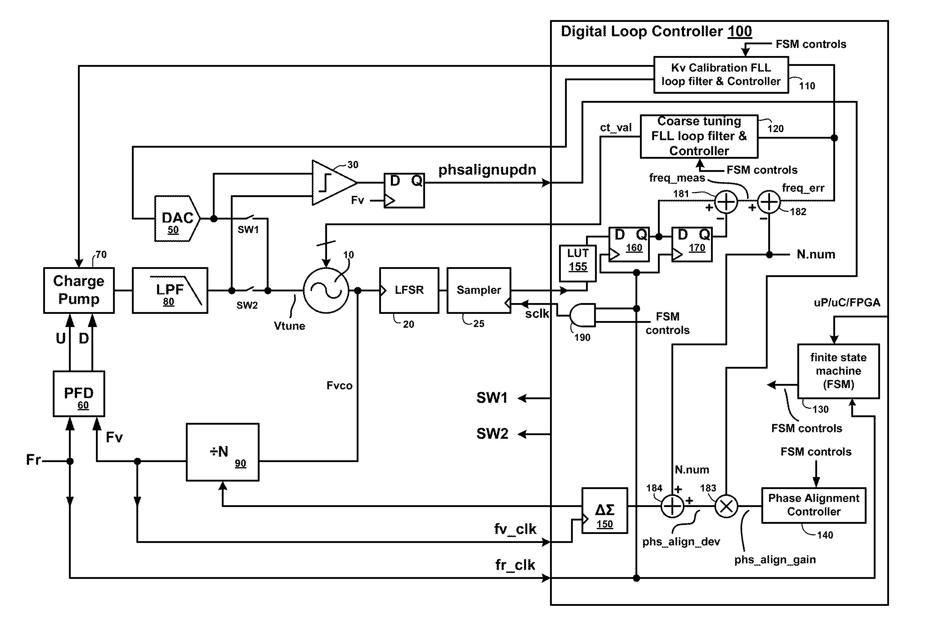
[0029]The present invention can be exemplified by the preferred embodiment as described hereinafter. An FLL system is used for coarse tuning a VCO and for calibrating for VCO Kv variation. The current invention provides a second feedback loop around the existing FLL. The secondary feedback loop forces the signal traveled on the route of NDIV-PFD-CP-LPF to essentially reach a desired lock condition before the FLL is switched off and the system enters PLL mode, thus achieving the goals of PLL calibration and fast locking.

[0030]FIG. 10 is a schematic diagram for a fast locking system for a fractional-N PLL according to the current invention. The FIG. 10 illustrates a VCO 10, a digital loop controller 100, a DAC 50, and the PLL components including a phase frequency detector 60, a charge pump 70, and a loop filter 80. The DAC 50 can also be an integrated part of the digital loop controller 100. This invention, as depicted in FIG. 10, discloses a secondary feedback loop including N-divid...


PUM


Abstract

The current invention provides a second feedback loop around the existing FLL, which forces the signal on the route of N-divider (NDIV), PFD, CP, and LPF to essentially reach their desired lock conditions before the FLL is switched off and the system enters PLL mode. This loop works by comparing the output voltage of the FLL DAC to the LPF output voltage, and then using this value to modulate the divider's dividing value. After the secondary feedback loop settles, output voltage from the LPF will be equal to the value that can drive the VCO to the desired lock frequency, and the phase error at the input side of the PFD produces a zero-average current to the charge pump. When this condition is set, the loop is essentially already in phase lock and the lock transient from the FLL mode to the PLL mode will be minimal.

Description

FIELD OF THE INVENTION[0001]This invention relates to an automatically calibrated fractional-N phase lock loop (PLL), and more particularly to an automatically calibrated fractional-N PLL with a shortened and improved initial lock time.BACKGROUND OF THE INVENTION[0002]Many PLL IC's with integrated LC voltage controlled oscillator (VCO) utilize a digitally programmable coarse tuning word in parallel with the fine tuning varactor. These PLL's require a digital coarse tuning system to select the appropriate digital coarse tuning word for the VCO. Furthermore, in order to reduce PLL bandwidth variation due to VCO tuning gain (Kv) variation, the VCO tuning gain Kv can be measured and compensated by adjusting charge pump current. As shown in FIG. 9, a frequency locked loop (FLL) system is employed to both select the appropriate coarse tuning digital word ct_val and to measure and compensate the VCO (106) tuning gain by modifying the charge pump 706 output current. An FLL differs from a PL...

Claims


Application Information

Patent Timeline
Patent Type & Authority Patents(United States)
IPC IPC(8): H03L7/06
CPCH03L7/1976H03L2207/06
Inventor BUNCH, RYAN LEE
Owner MSTAR SEMICON INC
Why Eureka
Try Eureka