Vector controlled leveling system for a forestry machine

a leveling system and forestry machine technology, applied in the direction of process and machine control, transportation items, propulsion unit arrangement, etc., can solve the problems of limiting unable to allow the undercarriage and turntable support, and operating the leveling mechanism on a slope can be especially difficult for even the most experienced operators, so as to achieve the effect of maximizing the operating envelope of the leveling mechanism

Active Publication Date: 2012-05-15
DEERE & CO
View PDF13 Cites 18 Cited by
  • Summary
  • Abstract
  • Description
  • Claims
  • Application Information

AI Technical Summary

Benefits of technology

[0010]The present invention provides a leveling control system for a forestry machine employing position sensors that relay information about the orientation of the carriage in relation to the swing-house assembly in order to control roll and pitch in a manner that maximizes the operating envelope of the leveling mechanism. The operating envelope of the leveling mechanism can be defined in terms of pitch and roll. The operating envelope can be a borderline plot of allowed pitch and roll combinations.

Problems solved by technology

This can be achieved by using shortened hydraulic cylinders that don't allow the undercarriage and turntable support to contact in any cylinder orientation.
Short cylinders, however, limit the operating envelope of the leveling mechanism.
However, limit switches abruptly cut off cylinder movement and create an operating envelope that is smaller than the operating envelope defined by actual interference / contact between the undercarriage and the turntable support.
Operating the leveling mechanism on a slope can be especially difficult for even the most experienced operators because the cab where the operator sits may be rotated 360° in relation to the undercarriage.

Method used


Image

  • Vector controlled leveling system for a forestry machine
  • Vector controlled leveling system for a forestry machine
  • Vector controlled leveling system for a forestry machine

Examples


Embodiment Construction

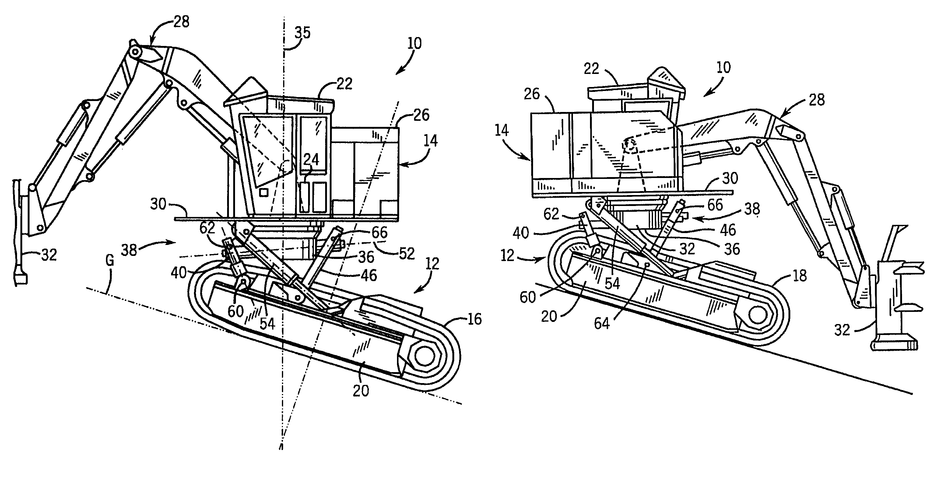
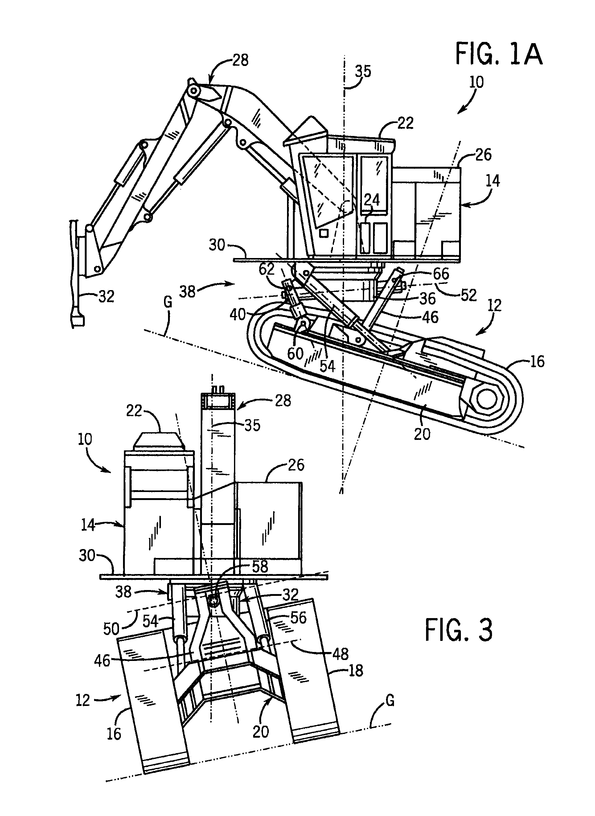
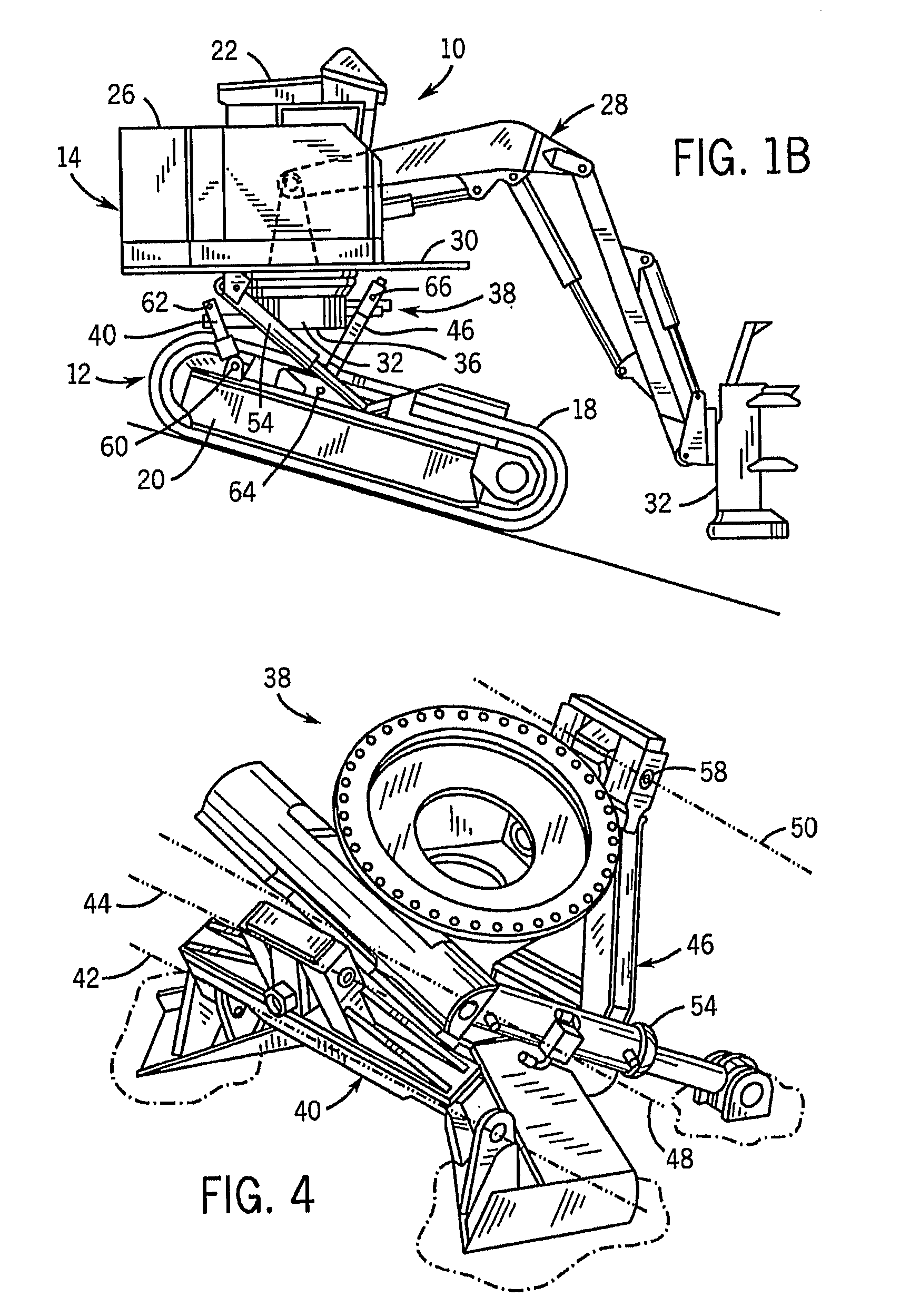
[0031]FIG. 1A illustrates a swing-to-tree forestry machine 10, particularly a feller / buncher, which includes a carriage 12 and a swing-house assembly 14. The carriage 12 includes tracks 16 and 18 which engage the ground G and are mounted to a carriage frame 20 so as to propel the machine 10 when they are driven. The drive mechanism of the tracks 16 and 18 and general structure of the frame 20 are conventional, may be of any suitable type and are not discussed in detail here.

[0032]The swing-house assembly 14 includes a cab 22 in which the machine operator sits and controls the machine, a controller 24, an engine 26 which provides power for driving the carriage and the hydraulic systems of the machine 10, and a boom 28, all of which are mounted to a turntable 30. At the end of the boom 28 opposite from the cab 22, a cutting head 32 is mounted for severing a tree to be cut. Many different types of cutting heads are available, a high speed disc saw felling head being illustrated. Anothe...


PUM


Abstract

The present invention provides a leveling control system for a forestry machine (10) employing position sensors that relay information about the orientation of the carriage (12) in relation to the swing-house assembly (14) in order to control roll and pitch in a manner that maximizes the operating envelop of the leveling mechanism (38). The angles of pitch and roll of the swing-house assembly (14) in relation to the carriage (12) are measured and / or calculated and a controller (24) limits operation of the leveling mechanism (38) to an operating envelop that may be described in terms of pitch and droll. The cylinders (54, 56) are decelerated gradually as the operating envelop is approached. The controller (24) can include an automatic leveling mode. The controller (24) can change the function of the fore, aft, left and right operator controls so that they are true from the operator's frame of reference regardless of the rotary position of the cab relative to the carriage (12).

Description

CROSS-REFERENCE TO RELATED APPLICATION[0001]This application claims the benefit of U.S. Provisional patent application Ser. No. 60 / 803,290, filed on May 26, 2006, and entitled “Vector Controlled Leveling System,” hereby incorporated by reference as if fully set forth herein.STATEMENT CONCERNING FEDERALLY SPONSORED RESEARCH OR DEVELOPMENT[0002]Not applicable.FIELD OF THE INVENTION[0003]This invention relates a leveling system for forestry equipment. This invention relates to a mechanism that connects a boom swing-house of a forestry machine to the frame of the ground engaging carriage of the machine, and more particularly to such a mechanism which is operated so as to level the swing-house in uneven or sloping terrain.BACKGROUND OF THE INVENTION[0004]Forestry machines for cutting, accumulating, processing and harvesting cut trees are well known in forestry operations. Typically, a forestry implement is mounted at the end of a boom or crane which has its other end mounted to a turntab...

Claims


Application Information

Patent Timeline
Patent Type & Authority Patents(United States)
IPC IPC(8): B62D33/073
CPCB60G17/0165E02F9/028B62D55/116B60G2300/06B60G2400/05B60G2300/45
Inventor O'HALLORAN, JAMESSCHULZ, DANIEL
Owner DEERE & CO
Why Eureka
Try Eureka