
Ski binding

a technology of ski binding and ski pole, applied in the field of ski pole, can solve the problems of low resistance to tipping, unsatisfactory example, and plate has to be relatively stiff, and achieve the effect of large resistance to tipping and stable behavior

Active Publication Date: 2012-05-22
MARKER DEUTLAND
View PDF12 Cites 18 Cited by
  • Summary
  • Abstract
  • Description
  • Claims
  • Application Information

AI Technical Summary

Benefits of technology

[0005]To date, there are either special touring bindings, with specific properties for touring and disadvantageous effects for downhill skiing, or there are downhill skiing bindings which have specific properties for downhill skiing but do not have any touring properties.
[0006]In recent times, a new skiing technique known under the term “free riding” is being increasingly used. In this case, as a rule, a wider ski than normal is used in order also to be able to travel off piste in deep snow. Great value is nevertheless placed on a stable behavior during skiing downhill, in particular on a large resistance to tipping. In order also to reach locations off piste, a touring property is also desirable, i.e. a possibility, by pivoting up the ski boot, to permit a cross-country running option, which generally presupposes a plate which also pivots.
[0007]The desirable specific properties of such a ski binding are contrary to each other, therefore there is not yet any satisfactory example of this in the prior art.BRIEF SUMMARY OF THE INVENTION
[0008]It is therefore the object of the invention to provide a ski binding which, in addition to good touring properties, also provides unrestricted downhill skiing options without the resistance to tipping of the ski binding being impaired. Nevertheless, the ski binding is not to be substantially heavier than a conventional ski binding, i.e. the plate which also pivots is either to be flexible and / or to be able to be composed of a lightweight material.
[0009]This object is achieved according to the invention by the characterizing features of patent claim 1.
[0010]Advantageous embodiments of the invention are described in the subclaims.

Problems solved by technology

However, the disadvantage of the known embodiment is that the plate has to be designed to be relatively stiff in order to show sufficient strength for downhill skiing and in order to prevent the plate from tipping in the front region in particular when the ski is tilted.
This results in a low resistance to tipping, said resistance to tipping being necessary in particular for downhill skiing.
The desirable specific properties of such a ski binding are contrary to each other, therefore there is not yet any satisfactory example of this in the prior art.

Method used


Image

  • Ski binding
  • Ski binding
  • Ski binding

Examples


Embodiment Construction

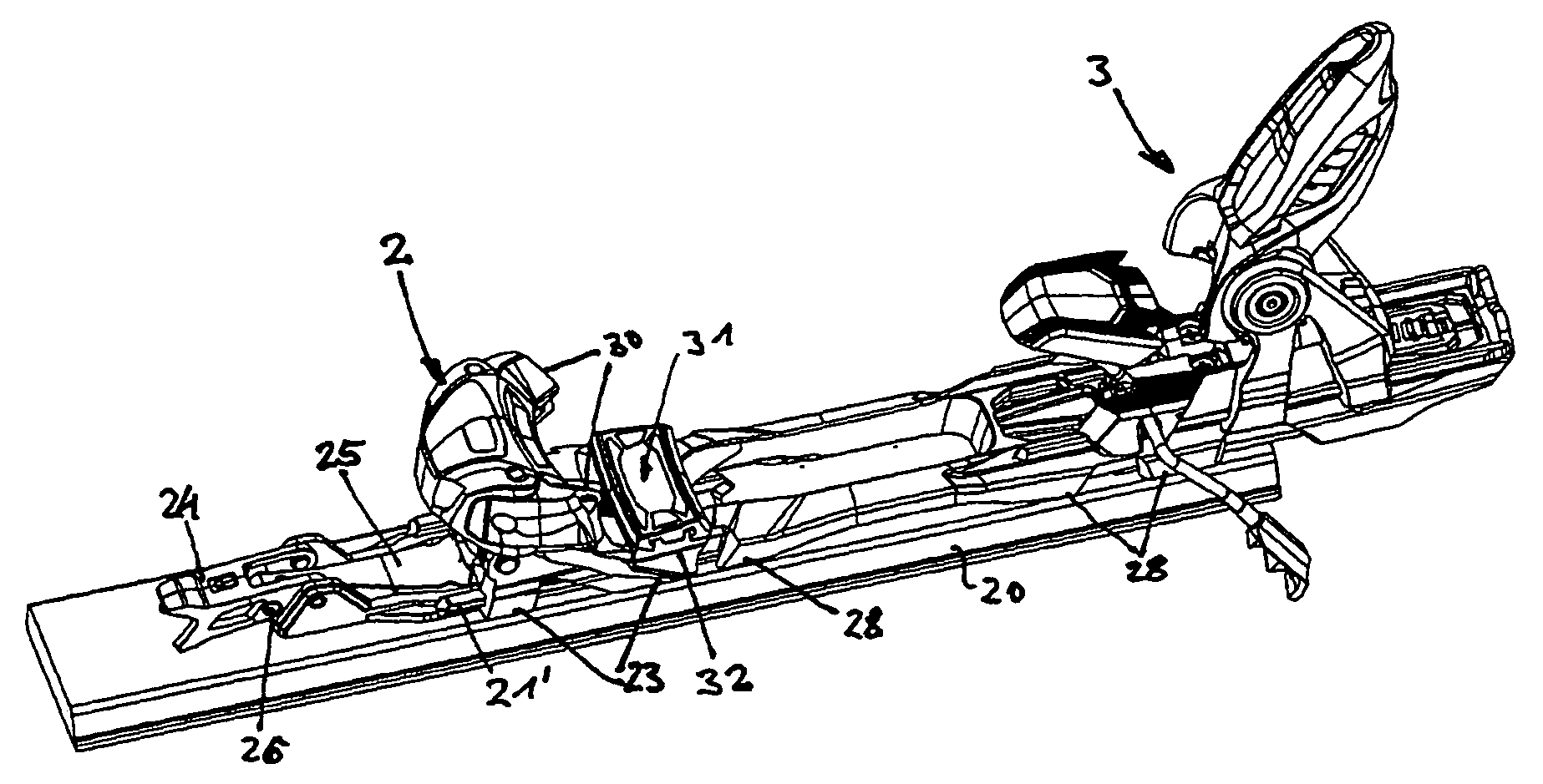
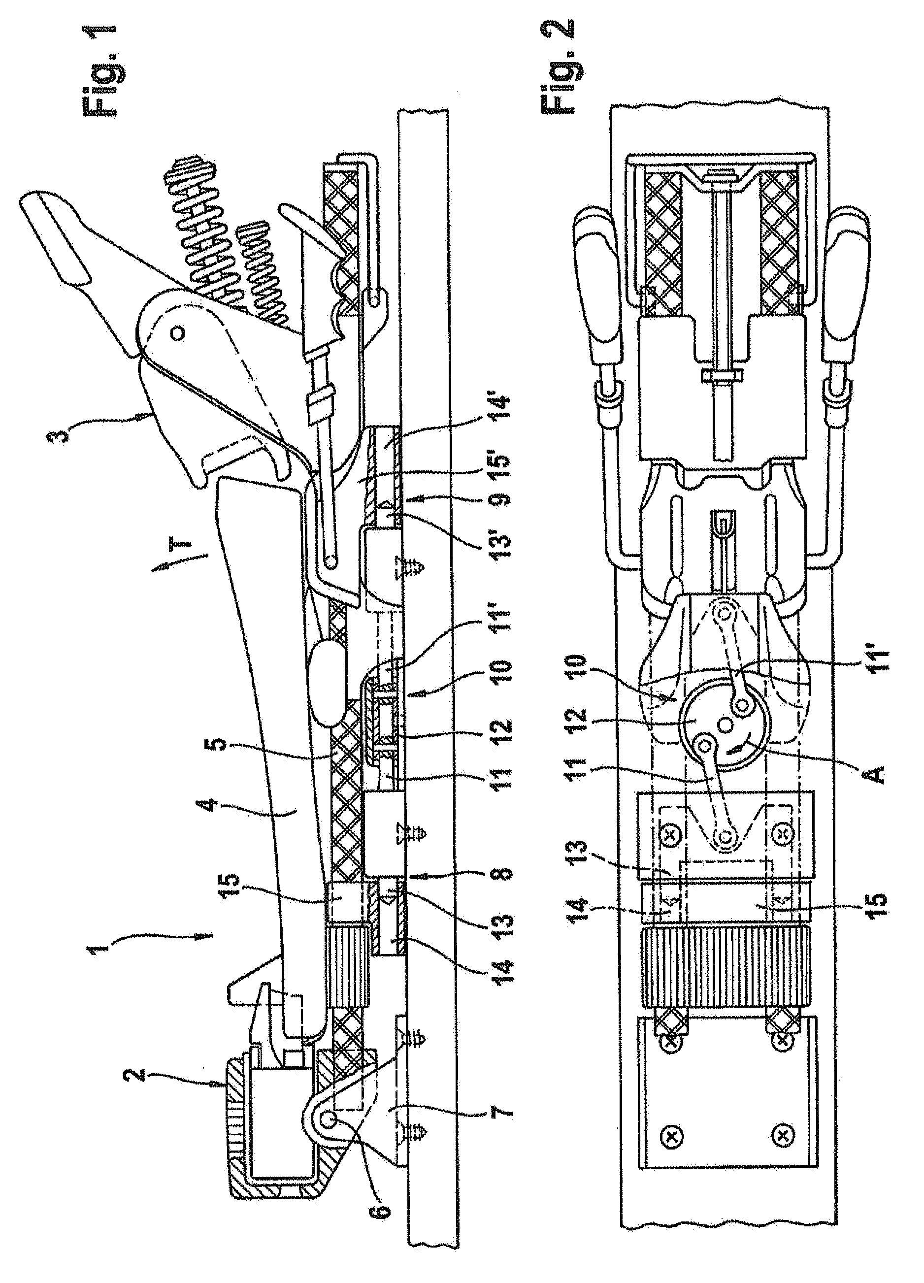
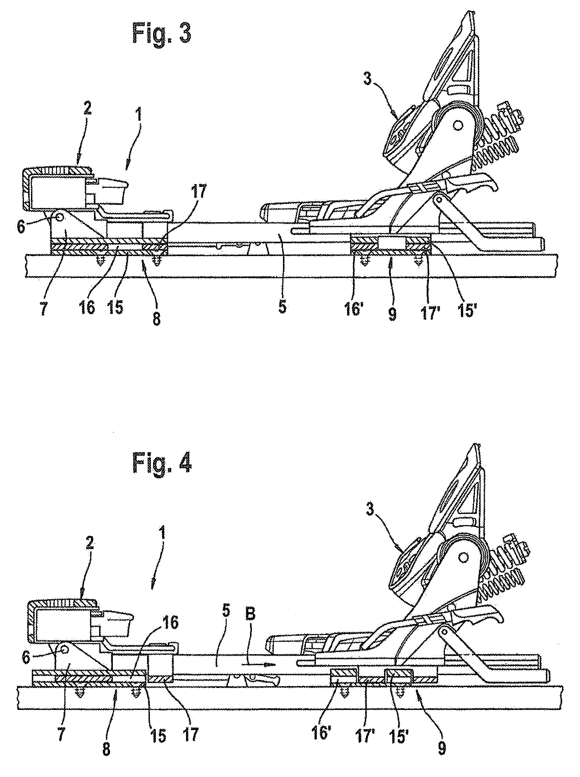
[0025]The ski binding 1 illustrated in FIG. 1 has a front sole holder 2 and a heel holder 3 which hold a sole 4 of a conventional downhill ski boot or of a touring ski boot on a plate 5. The release function, the mechanics and adjustability of said front sole holder 2 and of the heel holder 3 are basically known and are therefore not described in more detail here.

[0026]The plate 5 can be pivoted upward about a front axis 6, as known per se. In this case, said axis 6 is arranged transversely with respect to the longitudinal direction of the ski below the front sole holder 2 on a bearing part 7 fixed on the ski. In order to achieve said pivotability of the plate 5, the rear end of the plate 5 has to be freely movable upward in the arrow direction “T”, i.e. has to be able to be positioned from a locked position into an unlocked position.

[0027]In the exemplary embodiment illustrated in FIG. 1, the ski binding 1 according to the invention therefore has front locking elements 8 and rear l...


PUM


Abstract

A ski binding for downhill skiing and cross-country skiing has a plate which can be pivoted upwards in the front region about an axis located transversely to the longitudinal direction of the ski. A front ski binding and a rear heel holder for a ski boot or cross-country ski boot are fastened on the plate. At least one catch element which is arranged in front of, or in the region of, the rear sole holder can be used to secure the plate, in its rear region, on the abutment fitted on the ski. In addition, at least one catch element is arranged in the front region of the plate. The plate is fixed on the ski, and reinforced, in the manner of a conventional downhill ski binding by the further catch element in the front region of the ski binding and, in the locked state, is anchored at the front end and at the rear end, and at a number of locations therebetween, on parts of the ski or parts which have been fixed to the ski.

Description

CROSS REFERENCE TO RELATED APPLICATIONS[0001]This application claims priority based on DE 102005056526.3 filed Nov. 25, 2005, and International Application PCT / EP2006 / 068878 filed Nov. 24, 2006 which are hereby incorporated by reference in their entirety.TECHNICAL FIELD[0002]The invention is concerned with a ski binding.BACKGROUND OF THE INVENTION[0003]In the case of a ski binding of this type known from DE 26 60 145 C2, the plate, which is suitable for touring, is locked in its rear region in relation to two retaining clips fastened to the ski by means of two laterally arranged locking elements. In order to release the plate for the touring position, said locking elements have to be displaced or pivoted.[0004]An advantage of this arrangement of locking elements is that the latter are positioned within the binding region, i.e. between the front sole holder and the rear heel holder. In comparison to conventional locking elements of touring plates, which locking elements can be fixed ...

Claims


Application Information

Patent Timeline
Patent Type & Authority Patents(United States)
IPC IPC(8): A63C9/00A63C9/02A63C9/08A63C9/081A63C9/084A63C9/085
CPCA63C7/1013A63C9/001A63C9/005A63C9/02A63C9/0807A63C9/007A63C9/081A63C9/006A63C9/0844A63C9/0846A63C9/08542
Inventor MANGOLD, MICHAELTCHORSCH, THOMASKRUMBECK, MARKUS
Owner MARKER DEUTLAND
Learn More