Check patentability & draft patents in minutes with Patsnap Eureka AI!

Retraction mechanism for a drawer

a technology of retraction mechanism and drawer, which is applied in the direction of drawers, household applications, furniture parts, etc., can solve the problems of unstable tilting movement, and achieve the effect of convenient retraction and simple and easy way

Active Publication Date: 2012-05-22
KING SLIDE WORKS CO LTD
View PDF28 Cites 24 Cited by
  • Summary
  • Abstract
  • Description
  • Claims
  • Application Information

AI Technical Summary

Benefits of technology

The present invention provides a simple and easy way to install a retraction mechanism for a drawer in furniture. The mechanism includes a guiding member and a holding member, with an elastic member providing a pulling force to the holding member. The holding member has a first and second supporting portion, with a recess and a pin slot for engagement with the guiding member. The drawer has a pin that engages with the pin slot when the drawer is retracted into the furniture body. The elastic member pulls the holding member towards the furniture body to retract the drawer. The technical effect of the invention is to provide a convenient and effective way to install a retraction mechanism for a drawer in furniture.

Problems solved by technology

Without the groove, the tilting movement will be unstable.

Method used


Image

  • Retraction mechanism for a drawer
  • Retraction mechanism for a drawer
  • Retraction mechanism for a drawer

Examples


Embodiment Construction

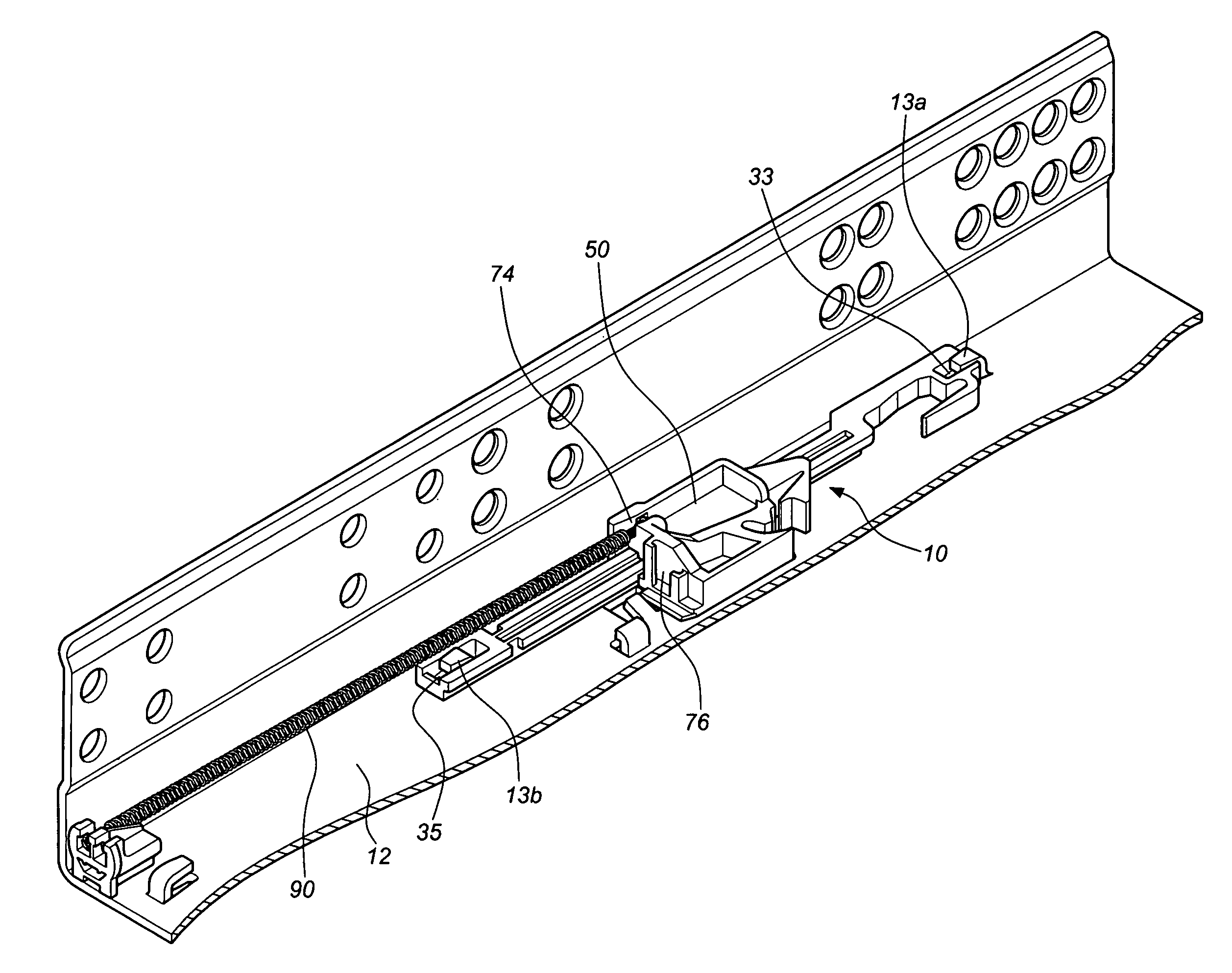
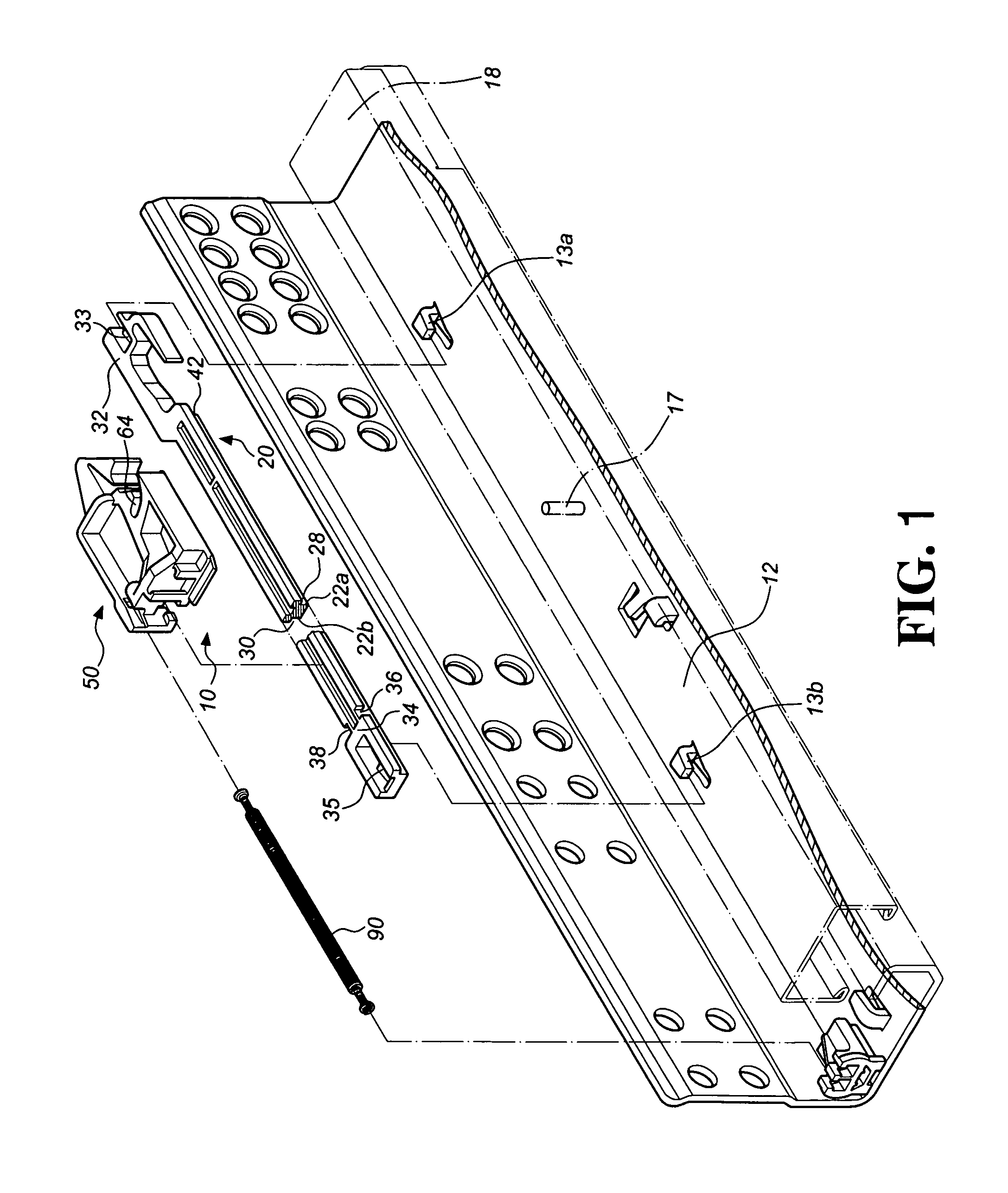
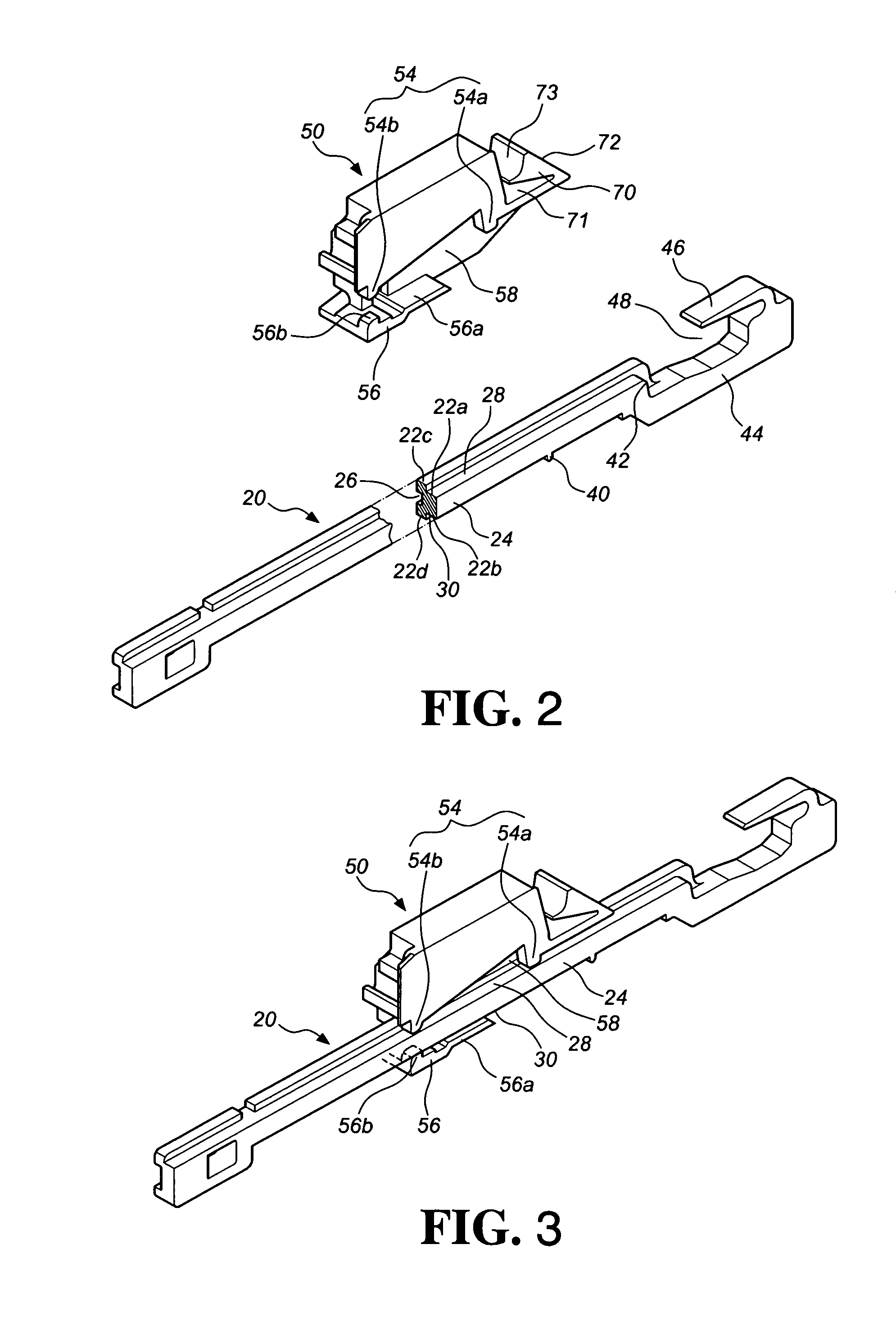
[0037]FIG. 1 is an exploded view of a retraction mechanism 10 and a stationary rail 12 according to a first preferred embodiment of the present invention. FIGS. 2 through 5 are schematic views of the retraction mechanism 10. As shown in FIGS. 1 through 5, the retraction mechanism 10 comprises a guiding member 20, a holding member 50 and an elastic member 90.

[0038]The guiding member 20 is secured to the stationary rail 12. The guiding member 20 comprises a first wall 22a, a second wall 22b, a side wall 24, a third wall 22c, and a fourth wall 22d. The side wall 24 is disposed between the first wall 22a and the second wall 22b. A groove 26 is defined among the side wall 24, the first wall 22a, and the second wall 22b. The third wall 22c extends from a portion of a surface of the first wall 22a. A first channel 28 is defined between the first wall 22a and the third wall 22c. The fourth wall 22d extends from a portion of a surface of the second wall 22b. A second channel 30 is defined be...


PUM


Abstract

A retraction mechanism for a drawer includes a guiding member, a holding member, and an elastic member. The guiding member includes a first wall, a second wall, a first channel and a second channel, a first end portion extending from first ends of the first and second walls. The first end portion includes a locking portion adjacent to the first channel. The holding member includes a pin slot, and a first supporting portion and a second supporting portion to hold against the first and second channels, respectively. The first supporting portion includes a first supporting leg corresponding to the locking portion. The drawer includes a pin for engaging with or disengaging from the pin slot when the drawer is pulled or pushed. The elastic member is adapted to act on the holding member. The drawer urged by the elastic member will be retracted into a furniture body when the drawer is moved to a predetermined position.

Description

BACKGROUND OF THE INVENTION[0001]1. Field of the Invention[0002]The present invention relates to a retraction mechanism, and more particularly to a retraction mechanism adapted to a drawer to assist the drawer in retracting into a furniture body.[0003]2. Description of Prior Art[0004]Retractable drawers have been widely used by the consumers, and there are a number of patents related to this issue, such as U.S. Pat. No. 5,207,781 to Rock, titled “Closing device for moving a drawer to a fully inserted position within a furniture body”; U.S. Pat. No. 5,364,179 to Brustle et al, titled “Closing device for Drawers”; U.S. Pat. No. 5,474,375 to Hollenstein et al, titled “Closing device for moving a drawer to a fully inserted position within a furniture body”; U.S. Pat. No. 5,240,318 to Schroder et al, titled “Device for holding a drawer in an article of furniture”; U.S. Pat. No. 5,302,016 to Lautenschlager et al, titled “Automatic pull-in mechanism for drawer guides”; U.S. Pat. No. 5,580,...

Claims


Application Information

Patent Timeline
Patent Type & Authority Patents(United States)
IPC IPC(8): A47B95/00A47B95/02
CPCA47B88/047A47B88/467
Inventor LIANG, HSIU-CHIANGCHEN, KEN-CHINGWANG, CHUN-CHIANG
Owner KING SLIDE WORKS CO LTD
Features
  • R&D
  • Intellectual Property
  • Life Sciences
  • Materials
  • Tech Scout
  • Unparalleled Data Quality
  • Higher Quality Content
  • 60% Fewer Hallucinations
Learn More