
Liquid ejecting apparatus and method controlling liquid ejecting apparatus

a liquid ejecting apparatus and liquid ejecting technology, applied in the direction of printing, other printing apparatus, etc., can solve the problems of difficult ejecting of minute liquid droplets, separation of tail-like portion, image quality deterioration, etc., and achieve the effect of preventing the columnar portion from growing excessively

Active Publication Date: 2012-05-22
SEIKO EPSON CORP
View PDF13 Cites 0 Cited by
  • Summary
  • Abstract
  • Description
  • Claims
  • Application Information

AI Technical Summary

Benefits of technology

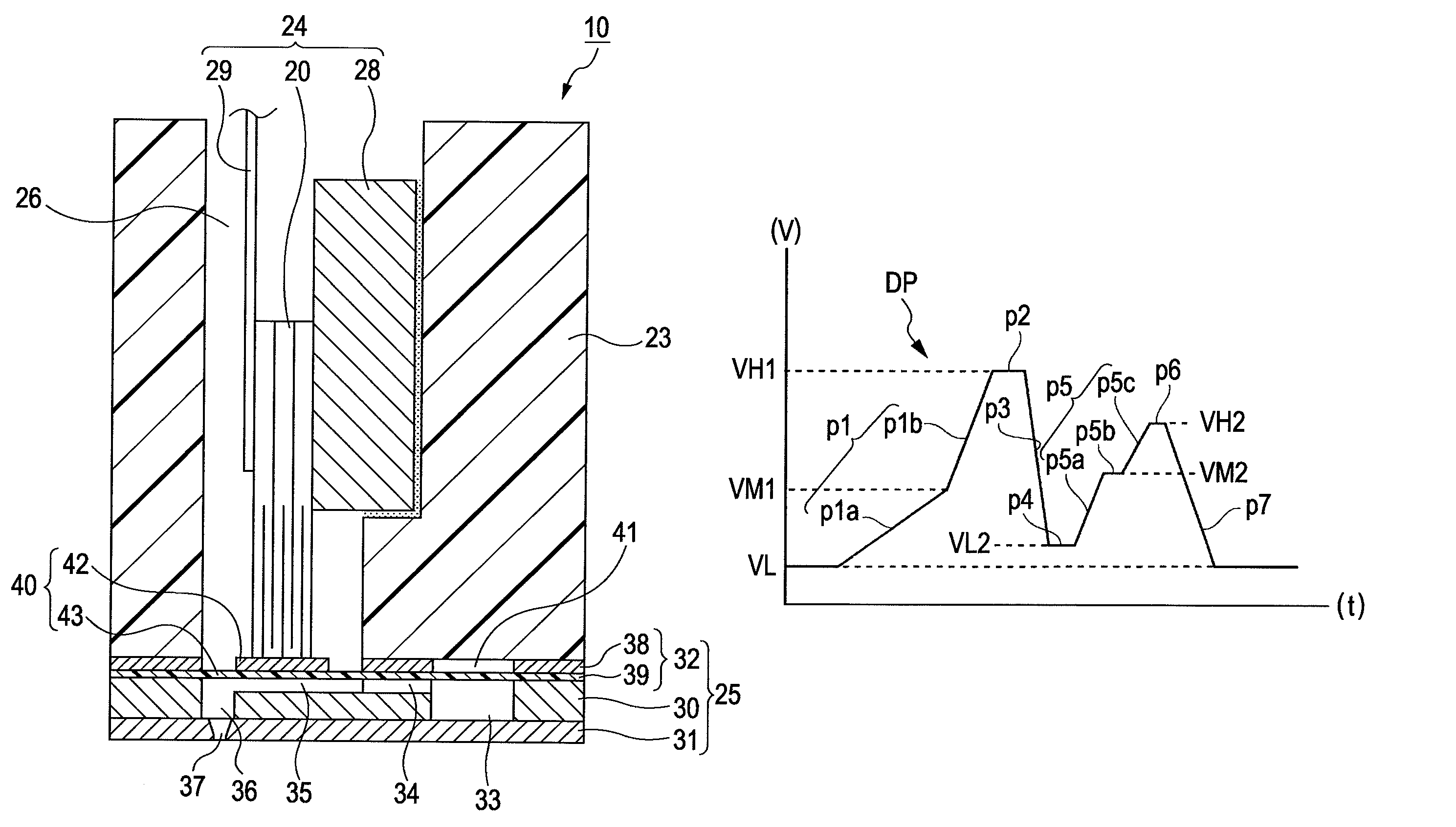
The invention provides a liquid ejecting apparatus that can make liquid droplets minute and prevent them from becoming a drawn tail. This is achieved by using a driving signal generating unit to repeatedly generate an ejection driving pulse used to eject the liquid from the nozzles. The ejection process includes a first pressure generating chamber expansion step of expanding the pressure generating chamber to draw a meniscus towards the pressure generating chamber side, a pressure generating chamber contraction step of contracting the pressure generating chamber to push the meniscus towards the liquid ejection side, and a second pressure generating chamber expansion step of expanding the pressure generating chamber to draw the meniscus towards the pressure generating chamber side again. The method also includes changing the potential change ratio of the pressure generating chamber during the expansion steps. This allows for a more precise control of the meniscus and prevents separation of dots.

Problems solved by technology

However, in the foregoing known driving pulse for expanding and contracting the pressure generating chamber to eject the ink, it is difficult to eject minute liquid droplets, when a liquid (hereinafter, referred to as a high-viscosity liquid) of which a viscosity is higher than that of a liquid such as ink used in a known household ink jet printer is used.
Moreover, a problem may arise in that the tail-like portion is separated from the main portion of the ink droplet and is not landed on the regular position (desirable position) of a landing target.
Therefore, a problem may arise in that an image quality deteriorates.
In particular, in the high-viscosity liquid, since the tail-like portion is separated into several pieces, the several separated pieces (satellite ink droplets or mist) may result in deteriorating the image quality to a great extent.

Method used


Image

  • Liquid ejecting apparatus and method controlling liquid ejecting apparatus
  • Liquid ejecting apparatus and method controlling liquid ejecting apparatus
  • Liquid ejecting apparatus and method controlling liquid ejecting apparatus

Examples


Embodiment Construction

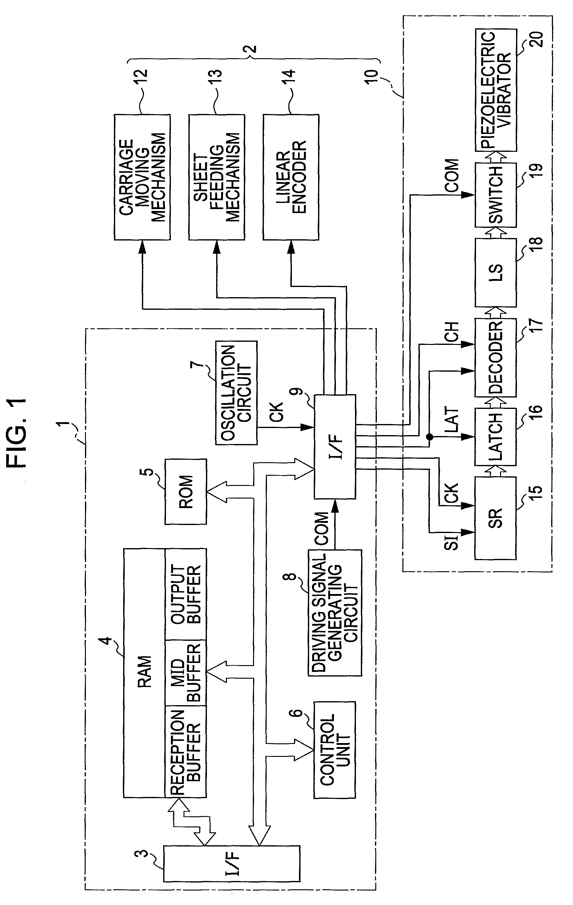
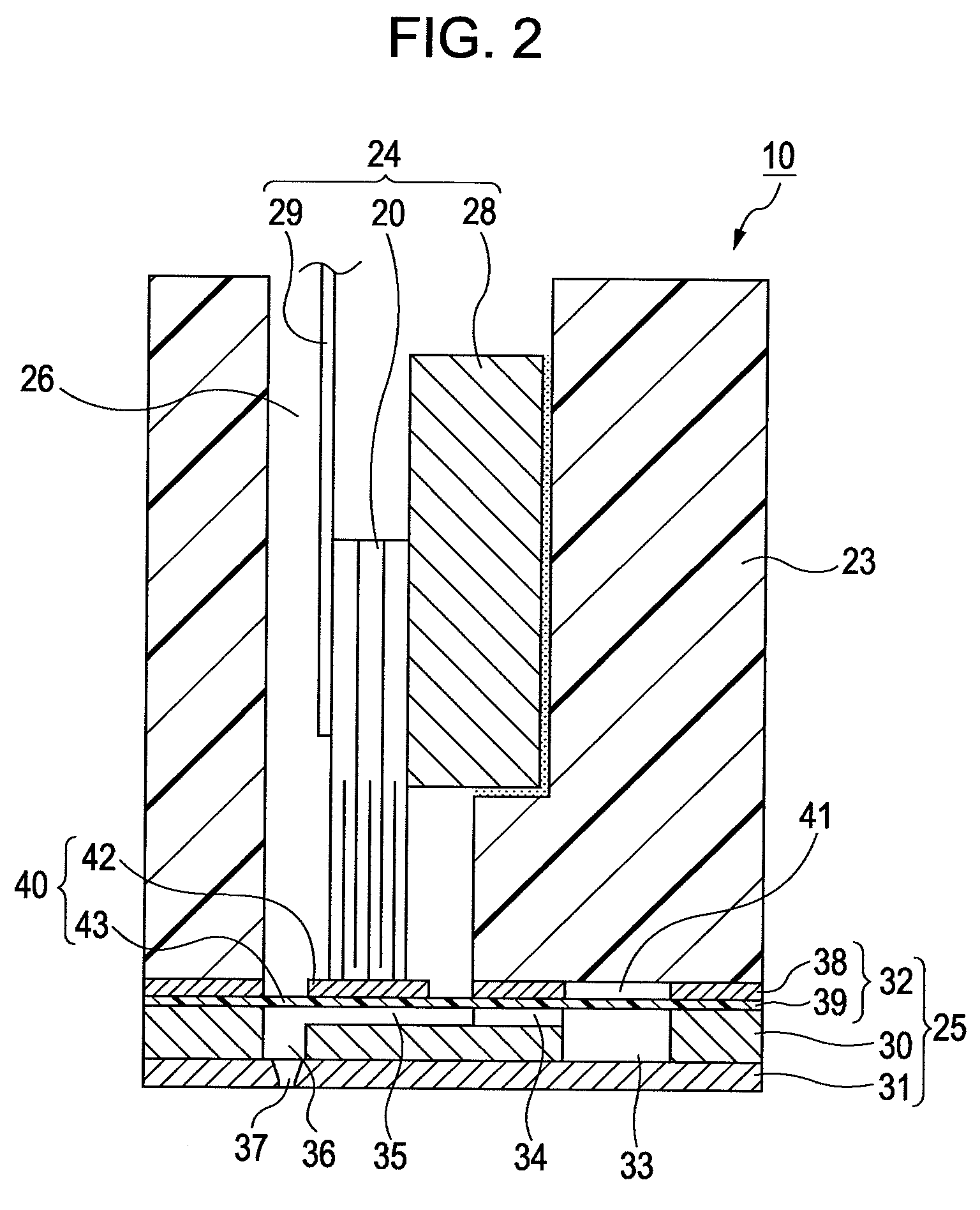
[0031]Hereinafter, a preferred embodiment of the invention will be described with reference to the accompanying drawings. The embodiment described below limits the invention to various forms, but the scope of the invention is not limited to the various forms by the following description, as long as the details limiting the invention are not particularly described. In addition, an ink jet printing apparatus (hereinafter, referred to as a printer) according to the invention will be described below as an example of a liquid ejecting apparatus.

[0032]FIG. 1 is a block diagram illustrating the electrical configuration of the printer. The printer includes a printer controller 1 and a print engine 2 as a whole. The printer controller 1 includes an external interface (external I / F) 3 which transmits and receives data to and from an external apparatus such as a host computer, a RAM 4 which stores a variety of data, a ROM 5 which stores a control routine or the like used to process the variety...


PUM


Abstract

A liquid ejecting apparatus includes: a liquid ejecting head which includes nozzles, pressure generating chambers communicating with the nozzles, and pressure generating elements causing a pressure change in a liquid of the pressure generating chambers and which ejects the liquid from the nozzles in response to an operation of the pressure generating elements; and a driving signal generating unit which drives the pressure generating elements to repeatedly generate a driving signal containing an ejection driving pulse used to eject the liquid from the nozzles. The ejection driving pulse has a pulse waveform containing a first pressure generating chamber expansion component which expands the pressure generating chamber to draw a meniscus toward the pressure generating chamber side, a pressure generating chamber contraction component which contracts the pressure generating chamber expanded by the first pressure generating chamber expansion component to push the meniscus toward the liquid ejection side, and a second pressure generating chamber expansion component which expands the pressure generating chamber contracted by the pressure generating chamber contraction component to draw the meniscus toward the pressure generating chamber side again. Each of the pressure generating chamber expansion components has a plurality of different potential change ratios.

Description

BACKGROUND[0001]1. Technical Field[0002]The present invention relates to a liquid ejecting apparatus such as an ink jet printer and a method of controlling the liquid ejecting apparatus, and in particular, to a liquid ejecting apparatus capable of controlling ejection of a liquid by applying a driving pulse contained in a driving signal to a pressure generating element and a method of controlling the liquid ejecting apparatus.[0003]2. Related Art[0004]A liquid ejecting apparatus is an apparatus which includes a liquid ejecting head capable of ejecting a liquid and ejects a variety of liquids from the liquid ejecting head. The representative example of the liquid ejecting apparatus is an image printing apparatus, such as an ink jet printer (hereinafter, simply referred to as a printer) which includes an ink jet printing head (hereinafter, simply referred to as a printing head) serving as a liquid ejecting head and prints an image or the like by ejecting and landing liquid-like ink on...

Claims


Application Information

Patent Timeline
Patent Type & Authority Patents(United States)
IPC IPC(8): B41J29/38
CPCB41J2/04581B41J2/04593
Inventor OZAWA, KINYAZHANG, JUNHUA
Owner SEIKO EPSON CORP
Learn More