
Camera suitable for use in a vehicle

a technology for vehicles and cameras, applied in the field of cameras, can solve problems such as image quality degradation, and achieve the effect of preventing the influence of moisture entering the camera or the housing

Active Publication Date: 2018-07-10
MAGNA ELECTRONICS
View PDF25 Cites 0 Cited by
  • Summary
  • Abstract
  • Description
  • Claims
  • Application Information

AI Technical Summary

Benefits of technology

The present invention provides a camera with a housing, optical system, and electrical image sensor, which prevents moisture from entering the camera and affecting the image quality. This is achieved by forming channels in the optical system to create air convection and prevent misting of the lenses. The camera can also be installed in an oblique position to achieve sufficient air convection and prevent misting. Additionally, a membrane is provided to facilitate the outward transport of moisture from the interior of the housing.

Problems solved by technology

The use of a camera module which is not configured in a fully leaktight manner can lead to water of condensation being formed in the optical path, or misting on the lenses of the optical system, and therefore to impairment of the image quality.

Method used


Image

  • Camera suitable for use in a vehicle
  • Camera suitable for use in a vehicle

Examples


Embodiment Construction

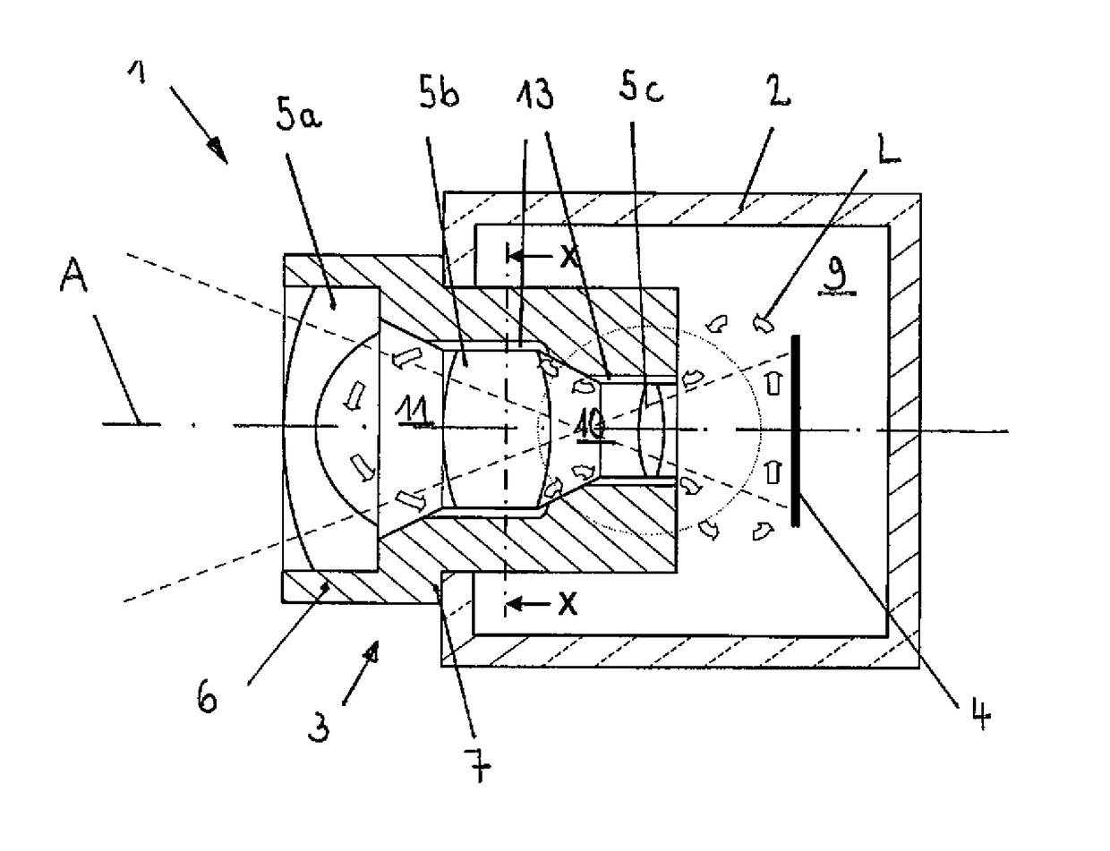
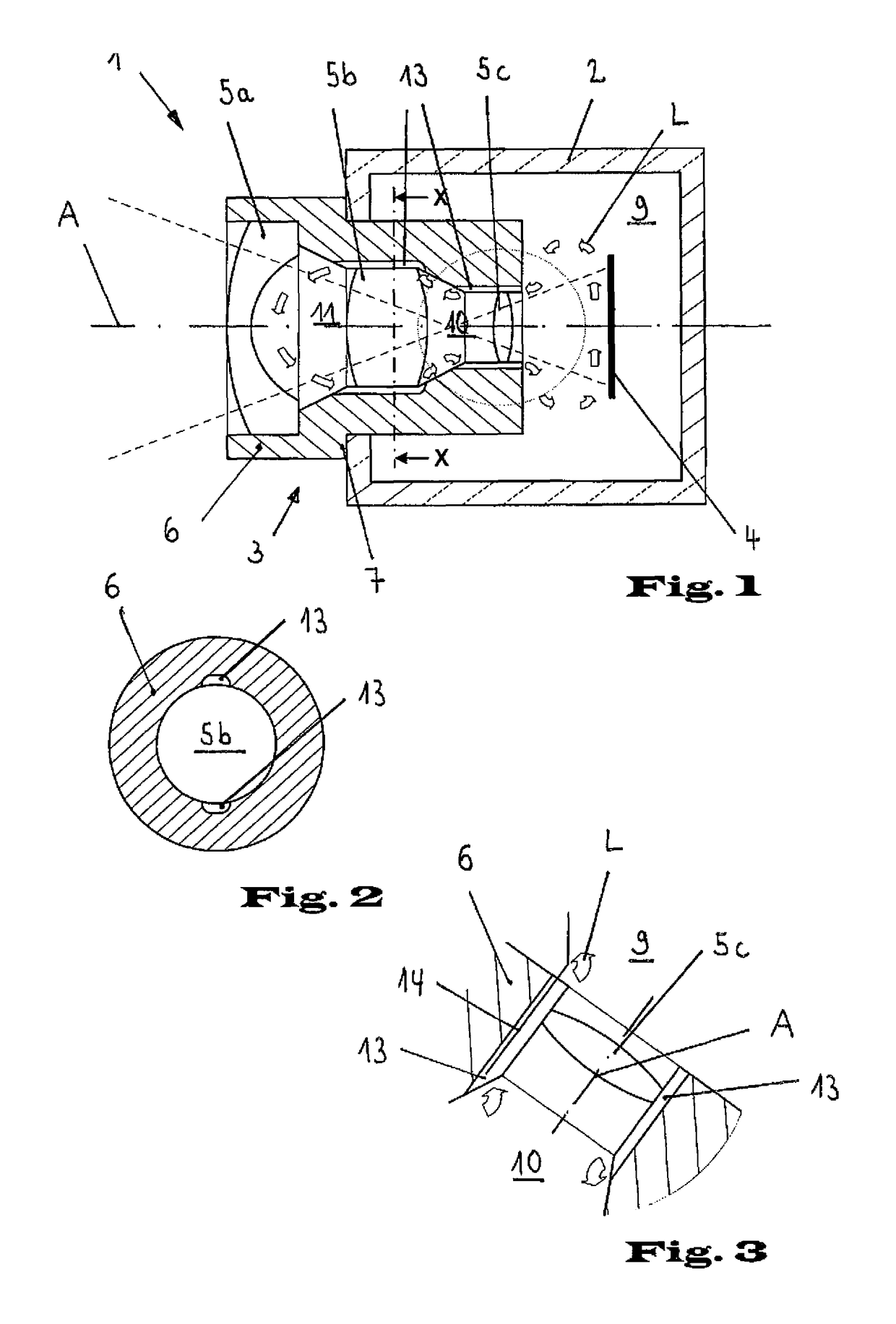
[0013]The camera 1 shown in the sectional representation in FIG. 1, which is used in particular for driver assistance functions and / or external monitoring of a motor vehicle, is installed in the horizontal installation position as shown, preferably in the region of the handle of a tailgate in the rear region of a motor vehicle or in the region of the cooling grille in the front region of a motor vehicle. The longitudinal axis, or optical axis A, of the camera in this case lies horizontally.

[0014]The camera 1 essentially comprises a housing 2, an optical system 3 and an electrical image sensor 4. The optical system 3 comprises an arrangement of a plurality of lenses 5a, 5b, 5c, which are arranged at a distance from one another in a tubular frame 6. The exemplary embodiment shown is formed with three lenses 5a, 5b, 5c arranged successively in an optical path. In order to receive the tubular frame 6, the housing 2 is provided with a reception opening. The tubular frame 6 bears tightly ...


PUM


Abstract

A camera having a housing, an optical system and an electrical image sensor, particularly for applications in the exterior region of motor vehicles, limits or prevents undesirable influences from moisture penetrating the camera or the housing. This is achieved by virtue of there being channels provided for air circulation in an interior of the optical system on the basis of the heating of air in the housing by operation of the image sensor, with the channels channeling air around lenses of the optical system. The channels may be along an internal wall of a lens frame of the optical system, and the channels may extend from an end portion of the lens frame at or near the image sensor to an internal space within the lens frame and between two adjacent lens elements of the optical system.

Description

CROSS REFERENCE TO RELATED APPLICATIONS[0001]The present application is a 371 national phase filing of PCT Application No. PCT / DE2012 / 000302, filed Mar. 22, 2012, which claims the filing benefit of German Patent Application No. 102011014991.0.FIELD OF THE INVENTION[0002]The invention relates to a camera having a housing, an optical system and an electrical image sensor.BACKGROUND OF THE INVENTION[0003]In the field of motor vehicles, camera systems in particular are used for driver assistance functions as well as for internal and external monitoring of the motor vehicle. For these applications in the internal, and in particular external, region of a motor vehicle, there are stringent requirements owing to external influences such as temperature variations, moisture influences and contamination. Conventionally, camera modules comprising an optical system and an electrical image sensor are formed as hermetically sealed units. The use of a camera module which is not configured in a full...

Claims


Application Information

Patent Timeline
IPC IPC(8): B60R11/04G02B27/00H04N5/225
CPCB60R11/04H04N5/2252G02B27/0006H04N23/51
Inventor KOPPE, ANDREAS
Owner MAGNA ELECTRONICS
Learn More