

Bearing unit and motor
a bearing unit and motor technology, applied in the direction of sliding contact bearings, mechanical equipment, mechanical energy handling, etc., can solve the problems of inability to produce an excellent effect, splashing, and inability to prevent the lubricating oil from leaking to the outside, and achieve excellent lubricating oil retaining performance, and reduced thickness
- Summary
- Abstract
- Description
- Claims
- Application Information
AI Technical Summary
Benefits of technology
Problems solved by technology
Method used
Image

Examples
first embodiment
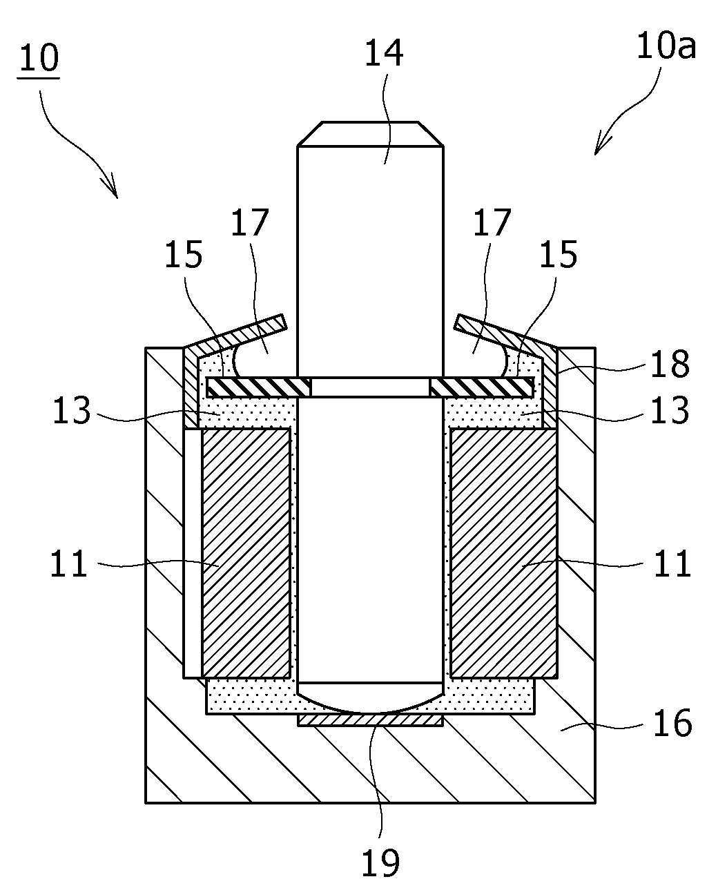
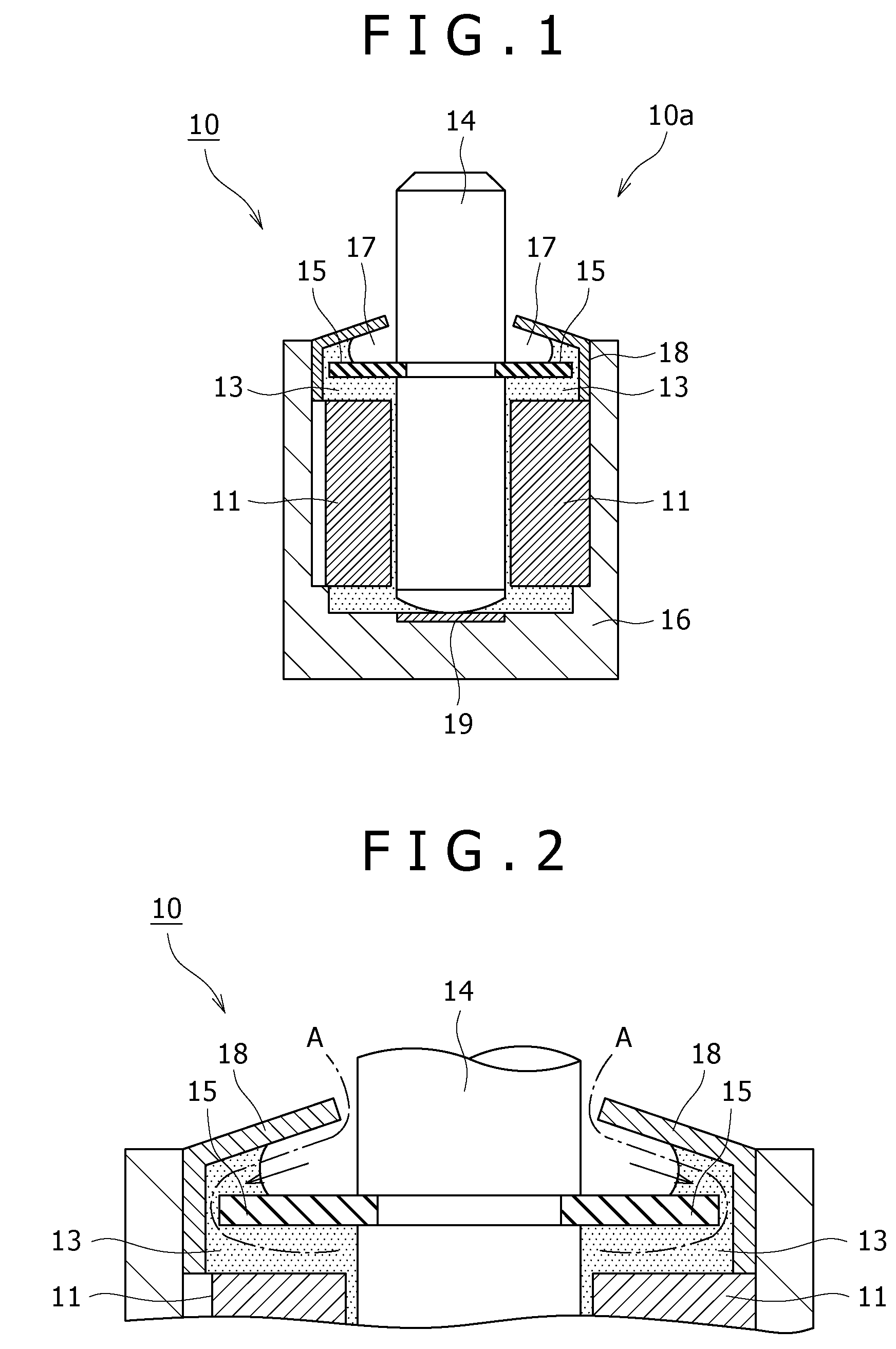
[0038]FIG. 2 is an enlarged schematic cross-sectional view for assistance in explaining the major portion of the bearing unit according to the The oil thrower ring 15 attached to the shaft 14 is a ring member made of metal or resin and fixedly fitted to the groove of the shaft 14. Alternatively, the oil thrower ring 15 may firmly be secured to the shaft 14 with an adhesive or by welding or the like as necessary.
[0039]The oil thrower ring 15 is perpendicularly attached to the shaft 14 to partition the gap between the upper surface of the slide bearing 11 and the gap-forming member 18. This forms the gap portion 17 on the upper side of the oil thrower ring 15 and a gap portion 13 on the lower side thereof.
[0040]There is provided a small gap between the end of the oil thrower ring 15 and the gap-forming member 18. Specifically, a lubricating oil flow passage A is formed which extends between the upper portion of the slide bearing 11 and the gap between the gap-forming member 18 and th...
second embodiment
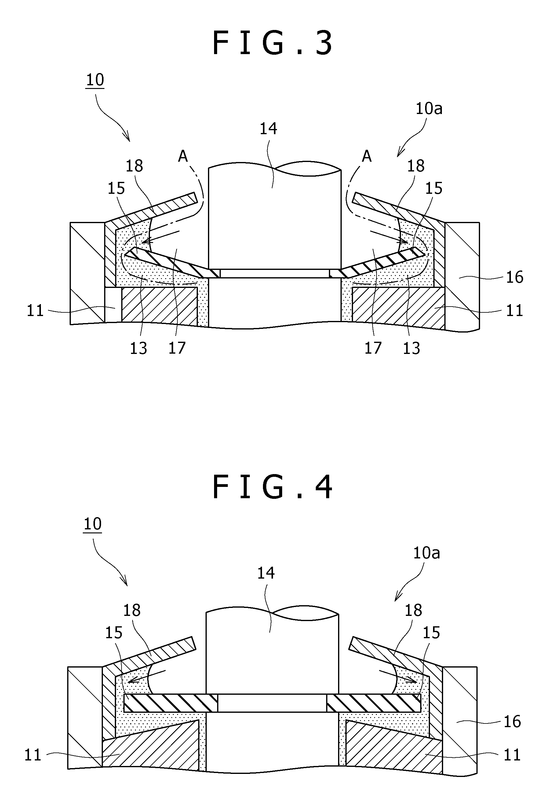
[0044]FIG. 3 is an enlarged schematic cross-sectional view for assistance in explaining a major portion of a bearing unit according to a A non-contact seal 10a of this embodiment further enhances lubricating oil-retaining performance resulting from surface tension compared with the non-contact seal provided for the bearing unit 10 shown in FIGS. 1 and 2.
[0045]The non-contact seal 10a is distinctive in providing a continuously tapered gap formed as below. A gap portion 13 between the upper portion of a slide bearing 11 and an oil thrower ring 15 is tapered in cross-section toward a sliding surface, i.e., the center of the shaft 14. In addition, a gap portion 17 between the oil thrower ring 15 and a gap-forming member 18 is progressively reduced in the distance therebetween with increasing distance from the sliding surface, i.e., the center of the shaft 14.
[0046]In the embodiment shown in FIG. 3, to form the continuously tapered gap described above, the oil thrower ring 15 is formed ...
third embodiment
[0048]Similarly to the above embodiments, the bearing unit 10 of the third embodiment forms the continuously tapered gaps. Thus, the tapered shape is increased in length to enhance performance for drawing the lubricating oil.
PUM
 Abstract
Description
Claims
Application Information