
Methods and apparatus for full-resolution light-field capture and rendering

a technology of lightfield and light field, applied in the field of full-resolution lightfield capture and rendering, can solve the problems of disappointingly modest resolution, conventional cameras failing to capture a large amount of optical information, and d image contains no information about the direction of light, etc., and achieve the effect of higher resolution

Active Publication Date: 2012-05-29
ADOBE SYST INC
View PDF72 Cites 177 Cited by
  • Summary
  • Abstract
  • Description
  • Claims
  • Application Information

AI Technical Summary

Benefits of technology

[0016]By focusing the microlenses on the image produced by the main lens, embodiments of the radiance camera are able to fully capture the positional information of the light-field. Embodiments of the full-resolution light-field rendering method may be used to render full-resolution images from flats captured by embodiments of the radiance camera, producing output images at a dramatically higher resolution than conventional light-field rendering techniques. Embodiments may render images at spatial resolutions that meet the expectations of modern photography (e.g., 10 megapixel and beyond), making light-field photography much more practical.

Problems solved by technology

However, this 2-D image contains no information about the direction of the light that strikes the photosensor.
Thus, conventional cameras fail to capture a large amount of optical information.
Not only is this a disappointingly modest resolution (any cell phone today will have better resolution), any particular rendered view only uses one out of every 3,720 pixels from the flat imagery.
The large disparity between the resolution of the flat and the rendered images is extraordinarily wasteful for photographers who are ultimately interested in taking photographs rather than capturing flat representations of the radiance.

Method used


Image

  • Methods and apparatus for full-resolution light-field capture and rendering
  • Methods and apparatus for full-resolution light-field capture and rendering
  • Methods and apparatus for full-resolution light-field capture and rendering

Examples


example results

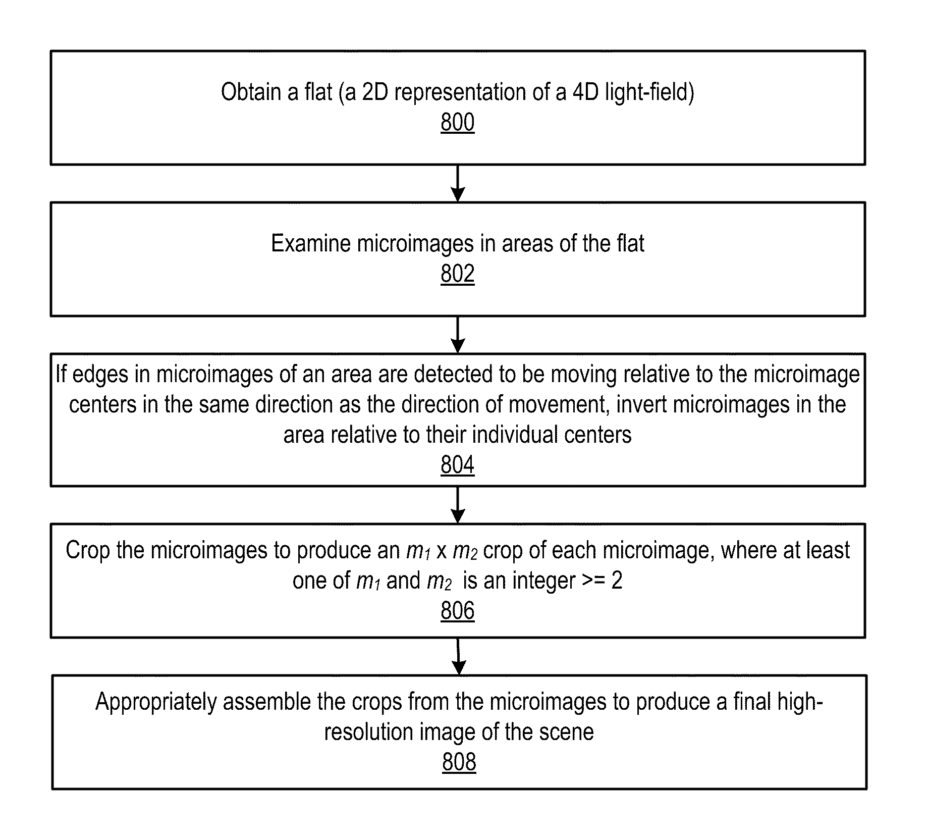
[0100]Some embodiments of a full-resolution radiance camera as described herein may be implemented in film cameras. Embodiments may, for example, be implemented in large-format film cameras. An example large-format film camera embodiment is illustrated in FIG. 8. One example embodiment may, for example, be implemented in large-format film camera using a 135 mm objective lens and 4×5 format film. A full-resolution radiance camera based on a large-format film camera rather than on a digital camera may be used for experimental purposes in order to avoid resolution constraint of digital sensors. However, film camera embodiments of the full-resolution radiance camera design are practical and may have practical applications. In conjunction with current high-resolution scanners used to digitize captured images from negatives or prints, large-format film camera embodiments are capable of 1 gigapixel, or even higher, resolution for the flat (2D) representation of the 4D radiance (the raw fla...


PUM


Abstract

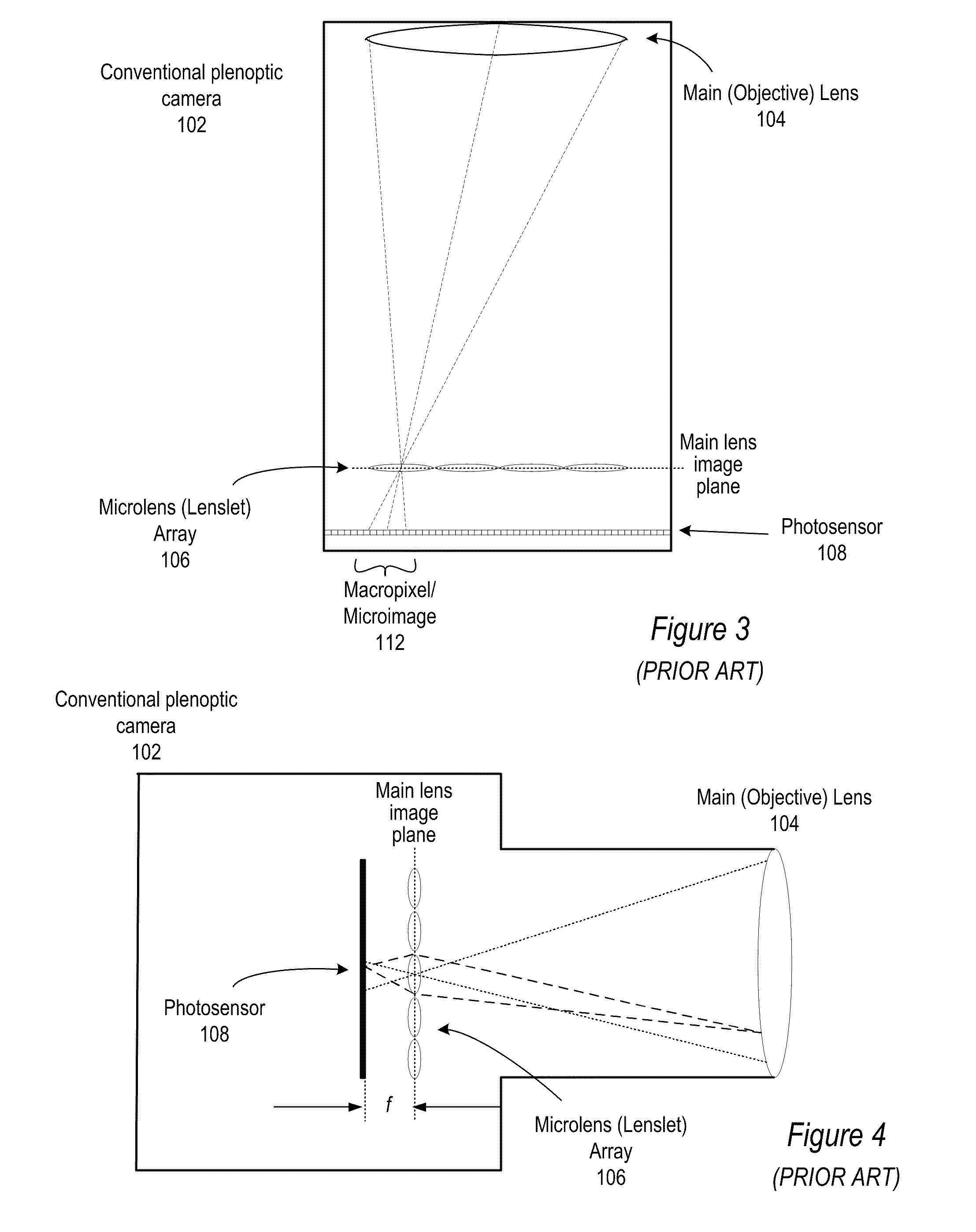
Method and apparatus for full-resolution light-field capture and rendering. A radiance camera is described in which the microlenses in a microlens array are focused on the image plane of the main lens instead of on the main lens, as in conventional plenoptic cameras. The microlens array may be located at distances greater than f from the photosensor, where f is the focal length of the microlenses. Radiance cameras in which the distance of the microlens array from the photosensor is adjustable, and in which other characteristics of the camera are adjustable, are described. Digital and film embodiments of the radiance camera are described. A full-resolution light-field rendering method may be applied to flats captured by a radiance camera to render higher-resolution output images than are possible with conventional plenoptic cameras and rendering methods.

Description

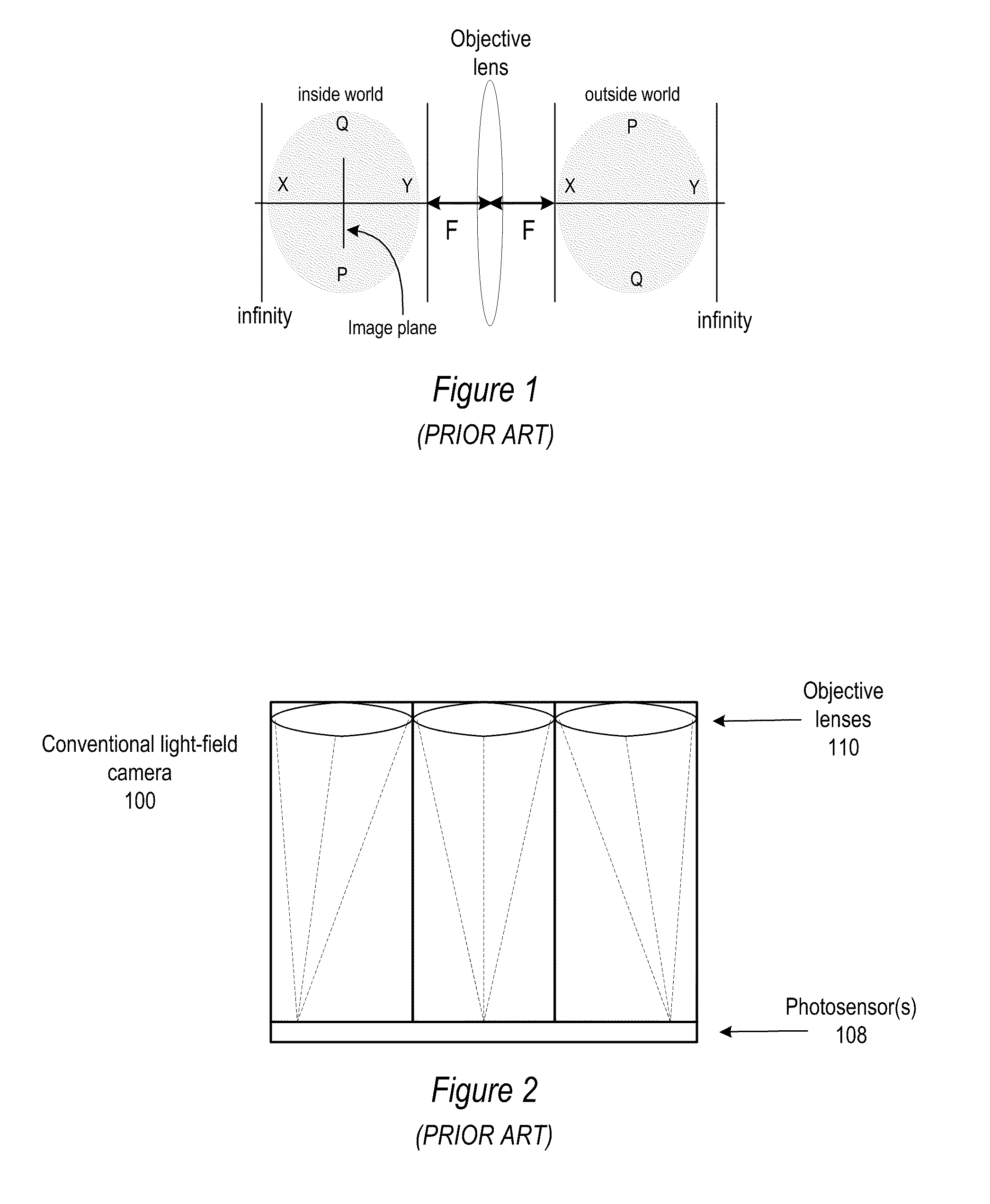
[0001]This application is a continuation-in-part of U.S. patent application Ser. No. 12 / 271,389 entitled “Methods and Apparatus for Full-Resolution Light-Field Capture and Rendering” filed Nov. 14, 2008 now U.S. Pat. No. 7,962,033, the content of which is incorporated by reference herein in its entirety, which claims benefit of U.S. Provisional Application Ser. No. 61 / 023,036 entitled “Full-resolution Lightfield Rendering” filed Jan. 23, 2008, the content of which is also incorporated by reference herein in its entirety.BACKGROUNDDescription of the Related Art[0002]In a conventional camera, the main lens maps the 3D world of the scene outside camera into a 3D world inside camera. FIG. 1 illustrates imaging in a conventional camera. “Inside world” represents inside the camera. The shaded oval regions represent the order of depths in the outside world, and the corresponding depths inside the camera. One particular image plane inside the camera is shown. The mapping of the 3D world of ...

Claims


Application Information

Patent Timeline
Patent Type & Authority Patents(United States)
IPC IPC(8): H04N5/228
CPCG03B15/00G03B35/08G03B35/24H04N5/2254G02B27/0075H04N23/80
Inventor GEORGIEV, TODOR G.LUMSDAINE, ANDREW
Owner ADOBE SYST INC
Learn More