Connection element

a technology of connecting elements and elements, applied in the field of connecting elements, can solve the problems of feared damage to wiper rubber, and achieve the effect of increasing surface pressure and small additional costs

Inactive Publication Date: 2012-06-05
ROBERT BOSCH GMBH
View PDF16 Cites 29 Cited by
  • Summary
  • Abstract
  • Description
  • Claims
  • Application Information

AI Technical Summary

Benefits of technology

[0005]However, in the case of wiper blades having a central spring, it is also advantageous to increase the surface pressure in the region of the base part locally. Although the claw roots are pressed to a pronounced extent into the lower region of the top strip of the wiper rubber, the pressure of the claws would have to be increased to such an extent, in order to generate an adequate surface pressure on the side of the base part, that damage of the wiper rubber is to be feared. As a result of the local increase in the surface pressure in the region of the base part, the fixing forces are distributed to a plurality of action points of the wiper blade, with the result that overloading at one point is not to be feared.
[0009]One particularly simple embodiment results if the base part is bent toward the wiper rubber between its ends, with the result that an increased surface pressure is produced on the wiper rubber in the central region of the connection element, if the claws are bent around the loadbearing element or the loadbearing elements during mounting. The size and magnitude of the curvature largely determines the magnitude of the local surface pressure. It can therefore be sufficient for the base part to have a bead in the region of a joint axis, which bead extends transversely with respect to the longitudinal direction and is pressed into the wiper rubber in the mounted position.
[0010]According to a further refinement, the base part can have claws at its ends, which claws are bent in the direction of the wiper rubber during the mounting and engage with their hooks into the wiper rubber. The local surface pressure can be modified by the length and shape of the hooks in such a way that an optimum compromise is achieved between the holding force and the loading of the wiper rubber. The claws can be formed integrally in the longitudinal direction on the ends of the base part or can be notched in the base part in the end regions. Both possibilities result in only small additional costs during the production of the connection element.

Problems solved by technology

Although the claw roots are pressed to a pronounced extent into the lower region of the top strip of the wiper rubber, the pressure of the claws would have to be increased to such an extent, in order to generate an adequate surface pressure on the side of the base part, that damage of the wiper rubber is to be feared.
As a result of the local increase in the surface pressure in the region of the base part, the fixing forces are distributed to a plurality of action points of the wiper blade, with the result that overloading at one point is not to be feared.

Method used


Image

  • Connection element
  • Connection element
  • Connection element

Examples


Embodiment Construction

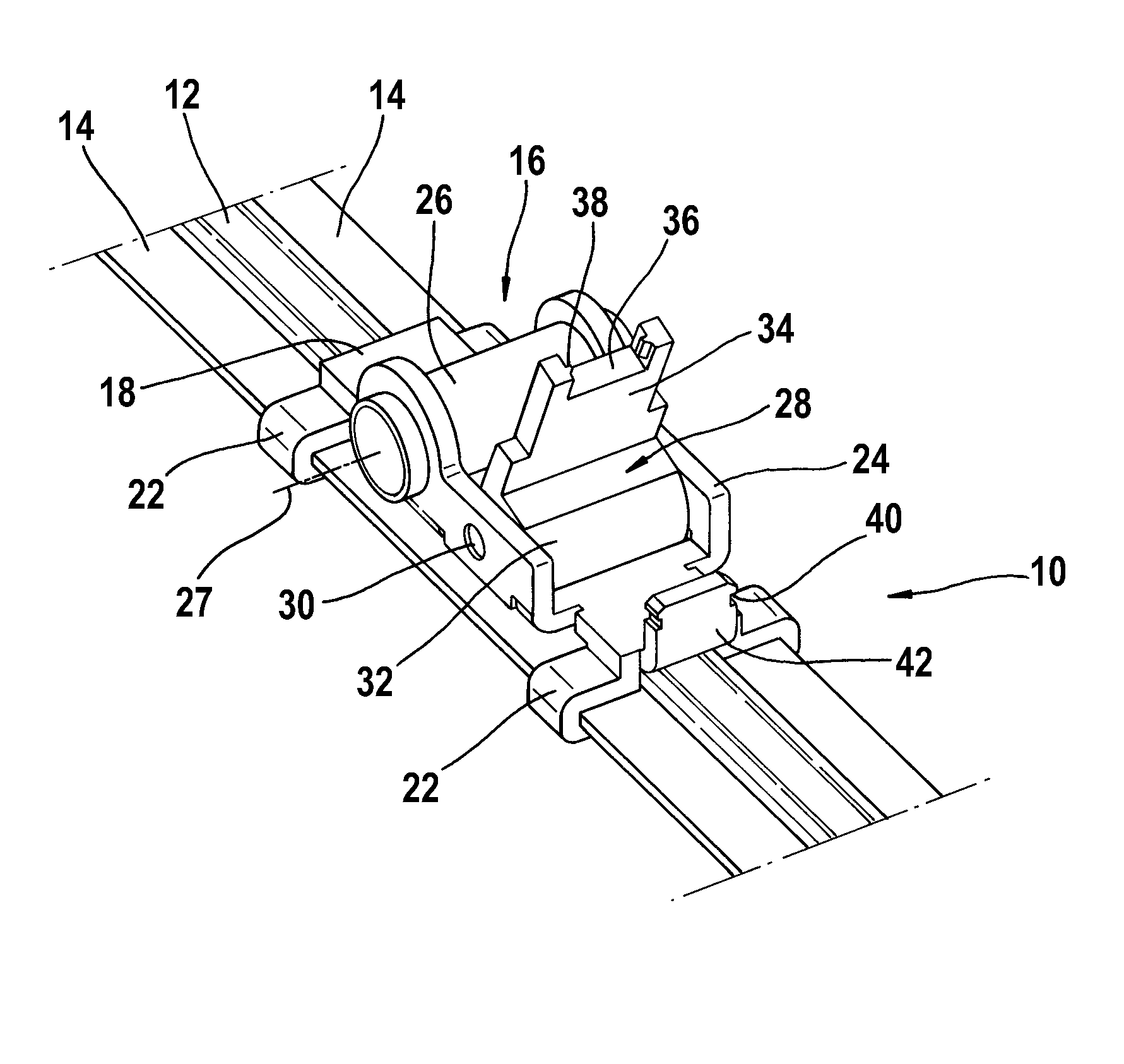
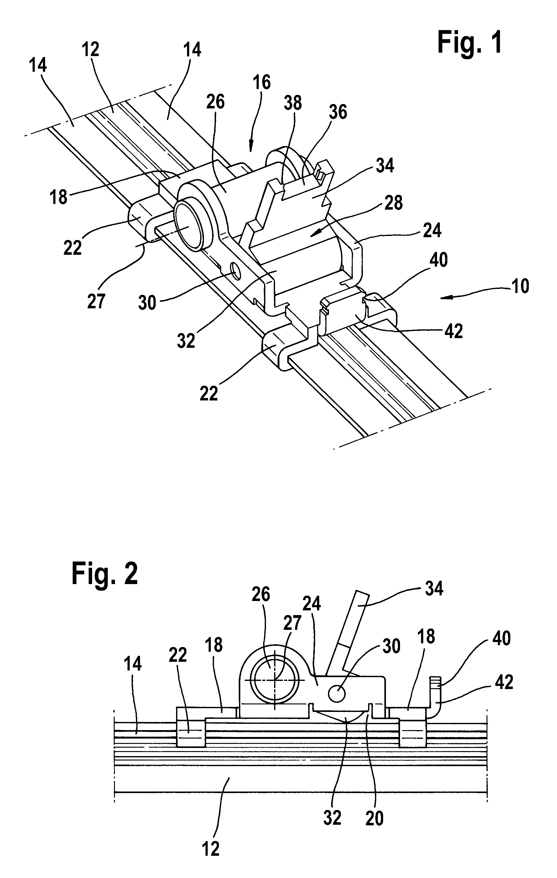
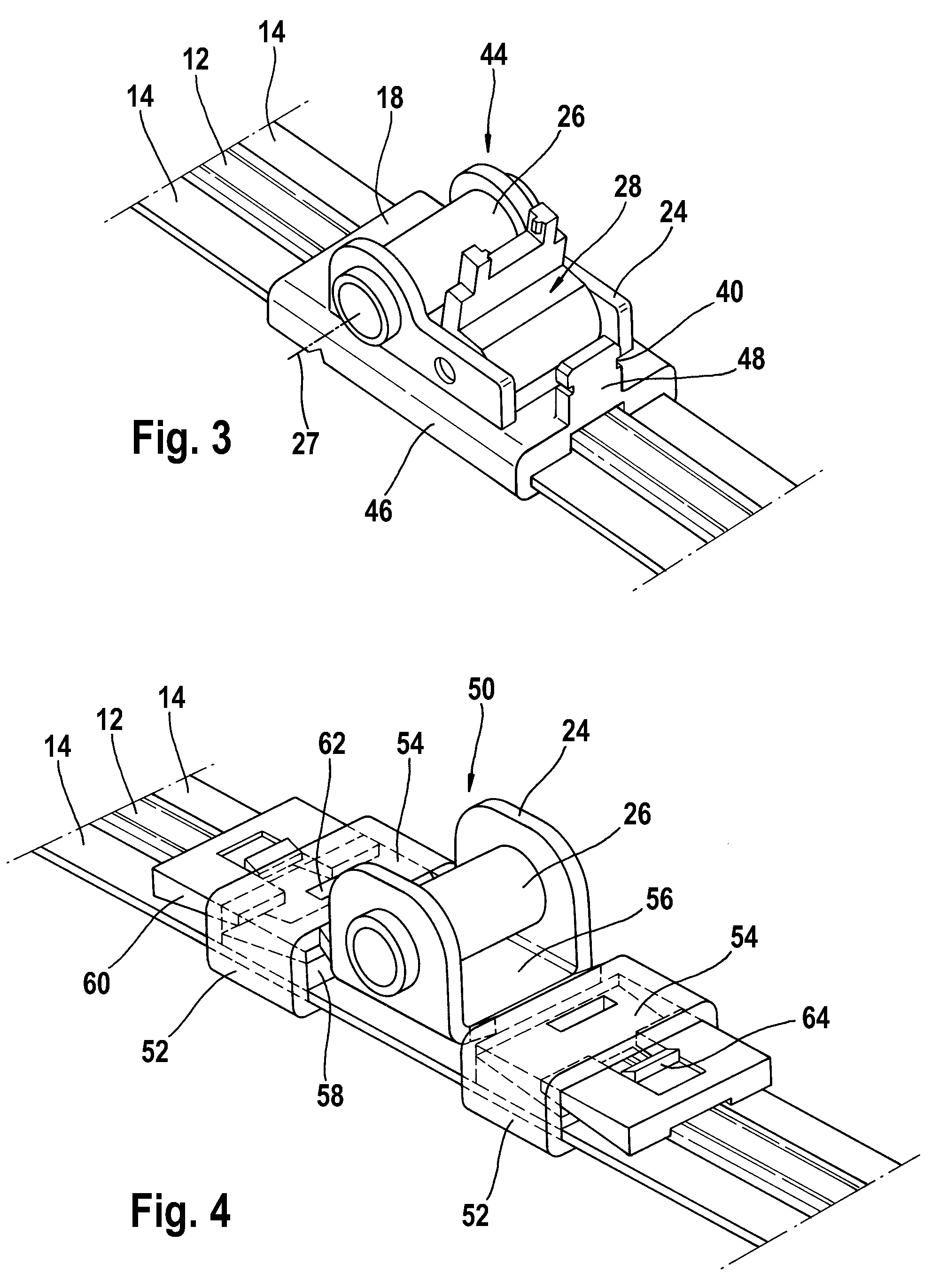
[0023]A wiper blade 10 having a wiper rubber 12 has two spring bars 14 which serve as loadbearing elements and are inserted into lateral longitudinal grooves of the wiper rubber 12. A connection element 16 which has a base part 18 and side walls 24 which are formed integrally on the latter is mounted on the wiper blade 10. Claws 22 which surround the spring bars 14 at the parts which protrude from the wiper rubber 12 are formed integrally on the base part 18 on the longitudinal sides.

[0024]The side walls 24 are connected to one another by a joint hub 26 which, together with a joint pin (not shown) of the wiper arm, forms a joint with a joint axis 27. In principle, the method of operation of the joint hub 26 and joint pin can be reversed, with the result that the side walls 24 are connected to one another by a joint pin and a joint hub 26 is provided on the wiper arm.

[0025]A clamping part 28 is mounted pivotably via bearing channels 30 in the side parts 24 parallel to the joint hub 2...


PUM


Abstract

The invention is based on a connection element (16, 44, 50, 66, 74, 80) for connecting a wiper blade (10), which has at least one spring rail (14) as a supporting element, to a wiper arm in an articulated manner, with the connection element (16, 44, 50, 66, 74, 80) having claws (22, 46, 52) which are integrally formed on the side of a base part (18) and, in the mounted state, surround and retain the spring rail (14) by the base part (18) being supported on a part of a wiper rubber (12) which is arranged between the spring rail (14) and the base part (18, 56, 68, 70). The invention proposes that the connection element (16, 44, 50, 66, 74, 80) has means (28, 58, 60, 68, 72, 76, 78, 82, 84) with which the surface pressure between the base part (18, 56, 68, 70) and the wiper rubber (12) is locally increased.

Description

BACKGROUND OF THE INVENTION[0001]The invention relates to a connection element.[0002]DE 198 35 065 A1 has disclosed a wiper blade, in which a spring bar is inserted as loadbearing element in a central longitudinal channel of a top strip. A connection element having a joint pin is seated on the top strip, in order for it to be possible to connect the wiper blade to a wiper arm in an articulated manner. The connection element bears with a base part against the top strip of the wiper rubber and is held by four claws which are formed integrally on opposite longitudinal sides of the base part and surround the top strip with the spring bar laterally and from below. During mounting, the claws are bent around the top strip and pressed together, so that a non-positive connection results between the connection element and the top strip.[0003]DE 10 2004 019 157 A1 has disclosed a wiper blade having two spring bars as loadbearing elements which are inserted into lateral longitudinal grooves of ...

Claims


Application Information

Patent Timeline
Patent Type & Authority Patents(United States)
IPC IPC(8): B60S1/38B60S1/40
CPCB60S1/3856B60S1/3867B60S1/40B60S1/3858B60S1/32
Inventor DE BLOCK, PETERHAEFELE, KLAUS-DIETERFATAN, BARTMERKEL, WILFRIEDCRABBE, RUDICRIEL, PAULWINDMOLDERS, ERICVAN BAELEN, DAVID
Owner ROBERT BOSCH GMBH
Why Eureka
Try Eureka