Metal gasket

a technology of metal gaskets and gaskets, which is applied in the direction of engine seals, sealing arrangements, machines/engines, etc., can solve the problems of lowering the sealing ability at the tightening portion, and achieve the effect of preventing the formation of pressure trace on the abutting surface of the cylinder head, improving the sealing ability, and reducing the thickness

Inactive Publication Date: 2006-02-07
ISHIKAWA GASKET CO LTD
View PDF15 Cites 15 Cited by
  • Summary
  • Abstract
  • Description
  • Claims
  • Application Information

AI Technical Summary

Benefits of technology

[0009]According to the metal gasket of the present invention having the structure described above, in the metal gasket wherein surface pressures at the abutting portions of a plurality of annular beads are increased, the surface pressures acting on the cylinder head or the cylinder block become uniform, so that a pressure trace is prevented from being formed on the cylinder head or the cylinder block. Also, the gasket base plate around the cylinder bore has a large thickness due to the shims to thereby improve the sealing ability.
[0010]According to the metal gasket of the present invention described above, while the surface pressures at the abutting portions of the annular beads are increased, the formation of the pressure trace on the abutting surface of the cylinder head can be prevented.

Problems solved by technology

Therefore, there has been a problem that the sealing ability at the tightening portion is lowered.

Method used


Image

  • Metal gasket
  • Metal gasket
  • Metal gasket

Examples


first embodiment

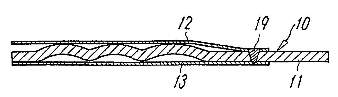
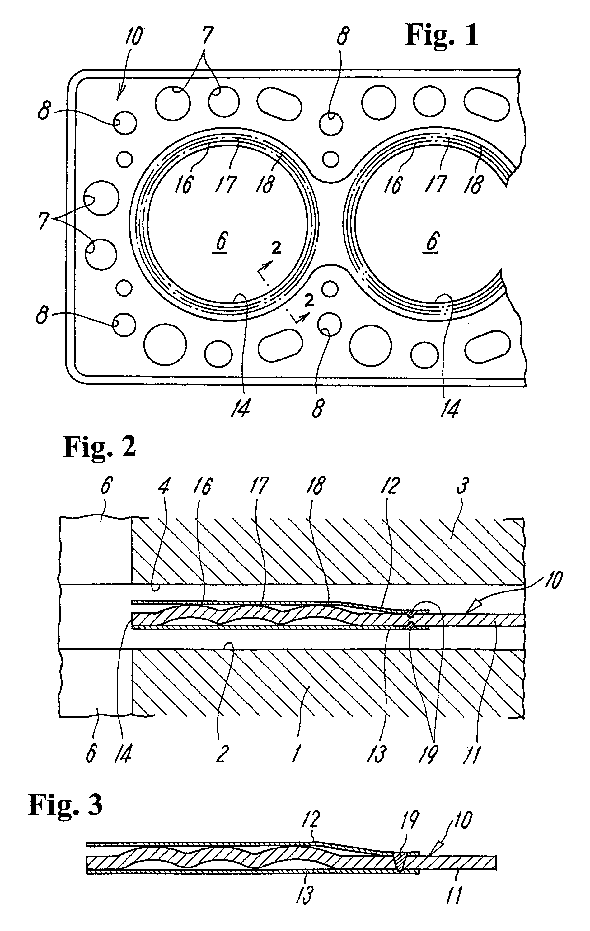
[0019]FIGS. 1 and 2 show a metal gasket 10 to be attached to a cylinder head attaching surface 2 of a cylinder block 1. The metal gasket 10 is attached to a contact portion between the cylinder block 1 and a cylinder head 3 to prevent combustion gas in a cylinder bore 6 provided therein and engine cooling water or oil circulating therein from leaking outside. The metal gasket 10 is formed of, as clearly shown in FIG. 2, a gasket base plate 11, and first and second shims 12 and 13 disposed on upper and lower surfaces of the gasket base plate 11, respectively. Also, the metal gasket 10 includes openings (combustion chamber holes) 14 substantially corresponding to the cylinder bores 6 formed in the cylinder block, and also, fluid holes 7 of cooling water and oil and holes 8 for tightening bolts, as apparent from a flat surface shape shown in FIG. 1.

[0020]The gasket base plate 11 is formed of a metal plate with a thickness t1 in the order of, for example, 0.2 to 0.3 mm, and includes mul...

third embodiment

[0028]In these metal gaskets, the shim 12 and 13 are welded only on portions where there is a risk of generating a pressure trace, or where the pressure trace is desired not to take place and, at the same time, the shim 42, 43 or 44 is selectively welded to a specific portion where there is a risk of generating the pressure trace, or where the pressure trace is desired not to take place. Thus, the surface pressure can be controlled at the required portions. Also, the necessary surface pressure can be obtained by the shims 42 and 43 or 44, and each shim functions as a stopper for stopping a movement of the metal gasket 40A, 40B, or 40C. The metal gaskets 40A, 40B, and 40C are effective not only for an automobile but also for other various applications.


PUM


Abstract

A gasket is interposed at a joining portion between two members. The gasket includes a gasket base plate having an opening through which fluid flows and a plurality of annular beads formed in a wave shape over a predetermined area extending outwardly from a hole edge of the opening; and at least one shim covering only the annular beads. The shims are laser-welded at a welding portion to cover the beads. Thus, the metal gasket does not have a pressure trace on abutting surfaces of a cylinder head.

Description

BACKGROUND OF THE INVENTION AND RELATED ART STATEMENT[0001]The invention relates to a metal gasket to be disposed between, for example, a cylinder block and a cylinder head of an internal combustion engine.[0002]In a metal gasket 100 disclosed in Japanese Patent Publication (KOKAI) No. 11-230355, as shown in FIG. 7, a gasket base plate 101 is provided with a plurality of annular beads 102 and 103 around a cylinder bore. When a cylinder head 104 and a cylinder block 105 are tightened, high surface pressures are generated at abutting portions between the cylinder head 104 and the annular bead 102 and between the cylinder block 105 and the annular beads 103 to improve the sealing ability thereat.[0003]However, in the metal gasket 100, a high surface pressure is generated at the abutting portion where the annular bead 102 or 103 abuts against the cylinder head 104 or the cylinder block 105, and forms a pressure trace at the abutting surface. When the tightening of the cylinder head 104 ...

Claims


Application Information

Patent Timeline
Patent Type & Authority Patents(United States)
IPC IPC(8): F02F11/00F16J15/02F16J15/08
CPCF16J15/0818F16J2015/0875F16J2015/0862F16J15/02F16J15/08
Inventor KINOSHITA, YUUICHI
Owner ISHIKAWA GASKET CO LTD
Why Eureka
Try Eureka