Web wrap device

a technology of web wrapping and web, applied in the field of web wrapping devices, can solve problems such as unreliability of these systems, and achieve the effect of improving the operation of the web wrapping

Active Publication Date: 2016-10-25
DEERE & CO
View PDF40 Cites 13 Cited by
  • Summary
  • Abstract
  • Description
  • Claims
  • Application Information

AI Technical Summary

Benefits of technology

[0006]Irrespective of whether the web is a net, paper, or a film, a safe gripping effect is achieved by sharp or thin elements, like teeth or spikes, or by sharp edges or the like which may enter the free spaces between the fibers of the web or which may penetrate the surface of a plastic or which may create a high surface pressure. The profile and the orientation of these elements will depend on the angle under which they hit the web and the material to be caught.
[0008]In order to increase the clamping effect, apertures like holes, slots, or simple depressions may be provided in the other element opposite to the protrusions, fingers, etc. in the moveable element. This will increase the contact surface area as well as the friction, since the web has to slip over sharp edges or the like.
[0009]When the moveable element is pivotable about a bearing that is spaced apart from the other element by at least 5 cm, two advantages are achieved: 1.) it is simple for an operator to insert the end portion of a new web, since hands may reach through the gap; and, 2.) obstacles or crop accumulation may pass through the track between the two elements without blocking the passage of the web. Of course 5 cm is a guiding dimension, which will be adjusted depending on the obstacles to pass and the need to push hands through. In the prior art device of EP 432 830 the gap between the two elements corresponds almost to the thickness of the web, which makes it difficult to feed a new web.
[0011]Providing a deflector like a bar, a string, sheet metal or the like may help in keeping the web off the moveable element, especially when the location and the path of the moveable element allow the tensioned web to press against it, which could have an impact on its clamping force.
[0012]In order to spread the web properly across the width of the article to be wrapped, like a bale, the leading edge of the other, stationary element is moderately curved convexly and in the extension of its delivery movement. This helps the border areas of the web to be stretched outwardly and possibly even to cover the corner, e.g. of a bale. Obviously the shape would be concave, if it is desired to achieve a concentration of the web towards the center of the article to be wrapped.
[0018]In a simple way the movement of the guard may be achieved by a spring or by gravity. Assuming that the web gets in contact with the guard before it is cut, it will improve the web wrap operation, if the guard does not hinder the web movement, e.g. by having rounded edges, etc.

Problems solved by technology

The problem is the unreliability of these systems, when either the web is not caught properly or undue forces appear during the pulling operation.

Method used


Image

  • Web wrap device
  • Web wrap device
  • Web wrap device

Examples


Embodiment Construction

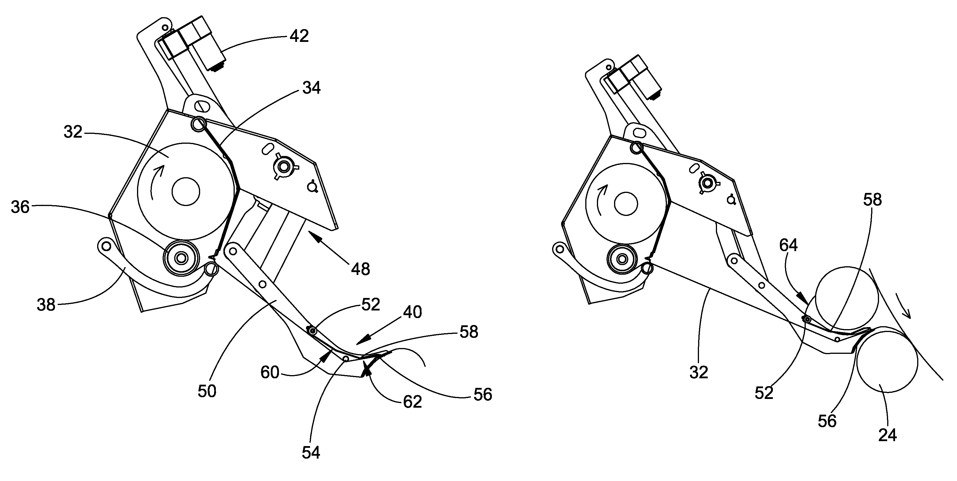
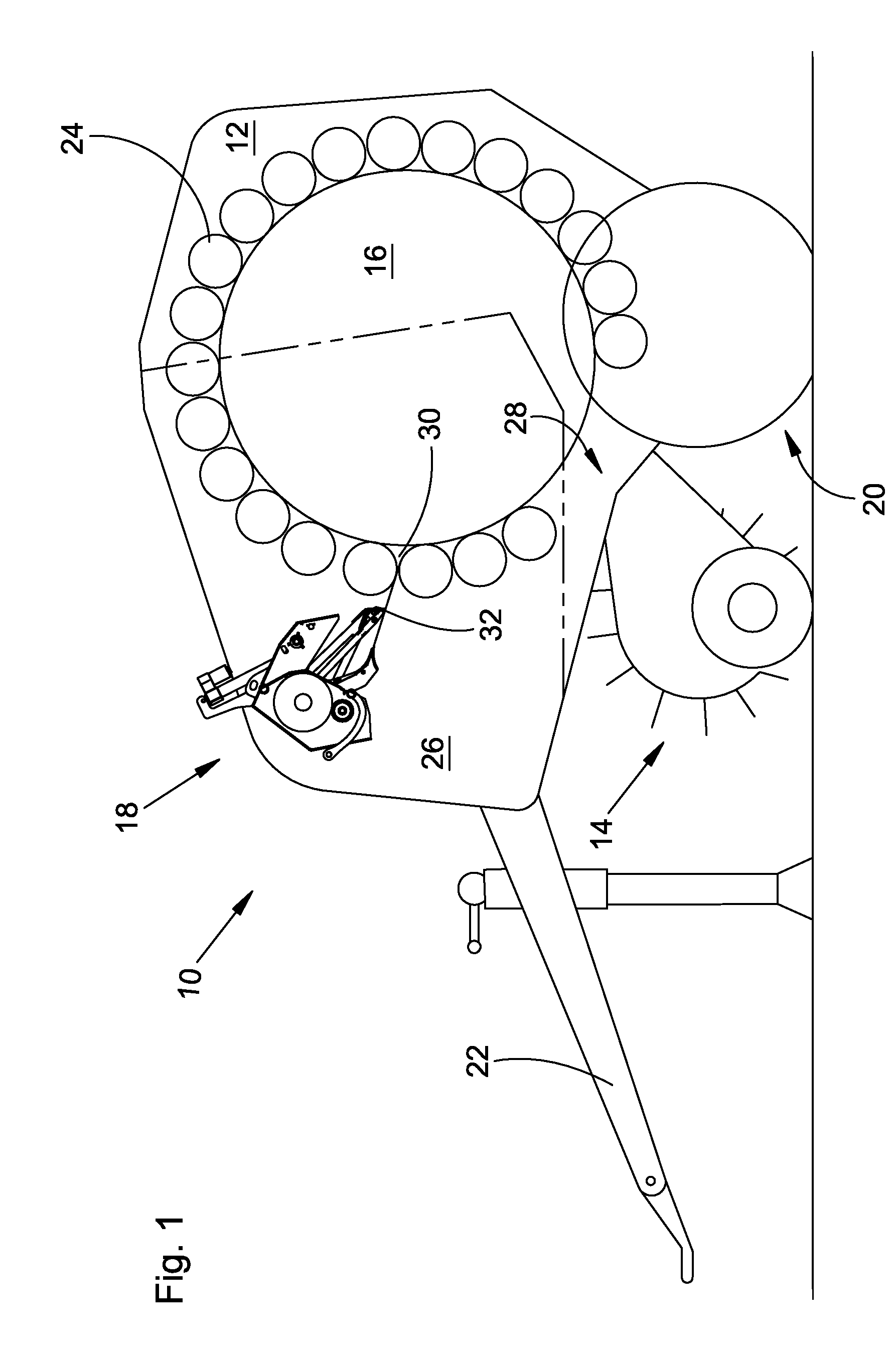
[0027]With reference now to the drawings it can be seen that FIG. 1 shows a round baler 10, which has a chassis 12, a pick-up 14, a bale chamber 16, a web wrap device 18, an axle with wheels 20, a tongue 22 and pressing means 24.

[0028]The round baler 10 is of an ordinary fixed chamber design, but could, alternatively, be a variable chamber baler.

[0029]The chassis 12 rests on the axle with wheels 20, carries the pick-up 14 and can be connected to a tractor or the like by means of the tongue 22. The chassis 12 has substantially one or multiple part side walls 26, which are spaced apart from each other to receive between them the bale chamber 16, the web wrap device 18 and the pressing means 24.

[0030]The pick-up 14 picks up crop from the ground and delivers it to the bale chamber 16 through a crop inlet 28 between pressing means 24.

[0031]The bale chamber 16 is covered substantially by the pressing means 24 on the circumference and by the side walls 26 on the face side. Besides the crop...


PUM

PropertyMeasurementUnit
radial distanceaaaaaaaaaa
angleaaaaaaaaaa
clamping forceaaaaaaaaaa

Abstract

A web wrap device is provided for a round baler. The device has a web carrier for pulling the web from a roll of web to a bale chamber. In a leading portion the web carrier has two elements at least one of which being moveable towards the other. The moveable element has a leading edge, which engages the web and is pulled by the tensioned web onto the other element, which increases the clamping effect. In addition a guard is provided to cover a knife during the wrapping mode, but to expose the knife to the web, when it should be cut.

Description

FIELD OF THE INVENTION[0001]This invention relates to a web wrap device having a web carrier movable between a rest position and a web delivery position. The web carrier has two elements that pinch the web therebetween, when moving towards the delivery position, with at least one of the elements being moveable with respect to the other.BACKGROUND OF THE INVENTION[0002]EP 432 830 discloses a net wrap device on a round baler with a so-called duck bill feeding device. This duck bill feeding device uses two nearly parallel plates, which are pressed against each other by means of a spring to hold the net, when it is pulled from a roll to a bale chamber.[0003]U.S. Pat. No. 6,886,307 teaches the use of a plate with a comb-like leading edge that grips the web and feeds it to a bale chamber.[0004]The problem is the unreliability of these systems, when either the web is not caught properly or undue forces appear during the pulling operation.SUMMARY OF THE INVENTION[0005]With the invention des...

Claims


Application Information

Patent Timeline
Patent Type & Authority Patents(United States)
IPC IPC(8): A01F15/07
CPCA01F15/0715A01F2015/0725
Inventor PAILLET, FREDERICGRESSET, PASCALVIAUD, JEANMENETRIER, MICHELFOURNIER, JEAN-FRANCOISMOREL, FREDERIC
Owner DEERE & CO
Why Eureka
Try Eureka