
Multi-stage controlled frequency generator for direct-drive wind power

a technology of direct-drive wind power and controlled frequency, which is applied in the direction of electric generator control, machine/engine, dynamo-electric converter control, etc., can solve the problems of increasing the size, weight and cost of the generator, and the ability of conventional direct-drive generators to control the output frequency at 60 hz,

Inactive Publication Date: 2012-06-12
HONEYWELL INT INC
View PDF59 Cites 3 Cited by
  • Summary
  • Abstract
  • Description
  • Claims
  • Application Information

AI Technical Summary

Benefits of technology

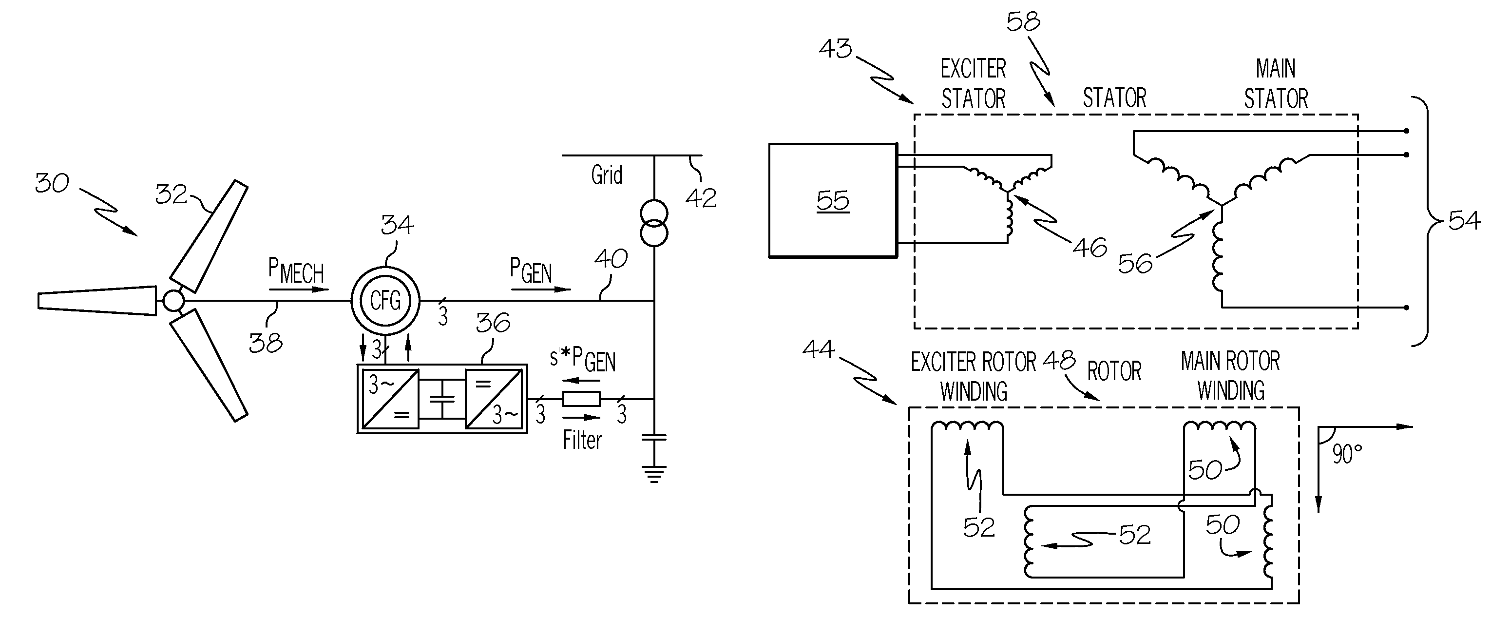
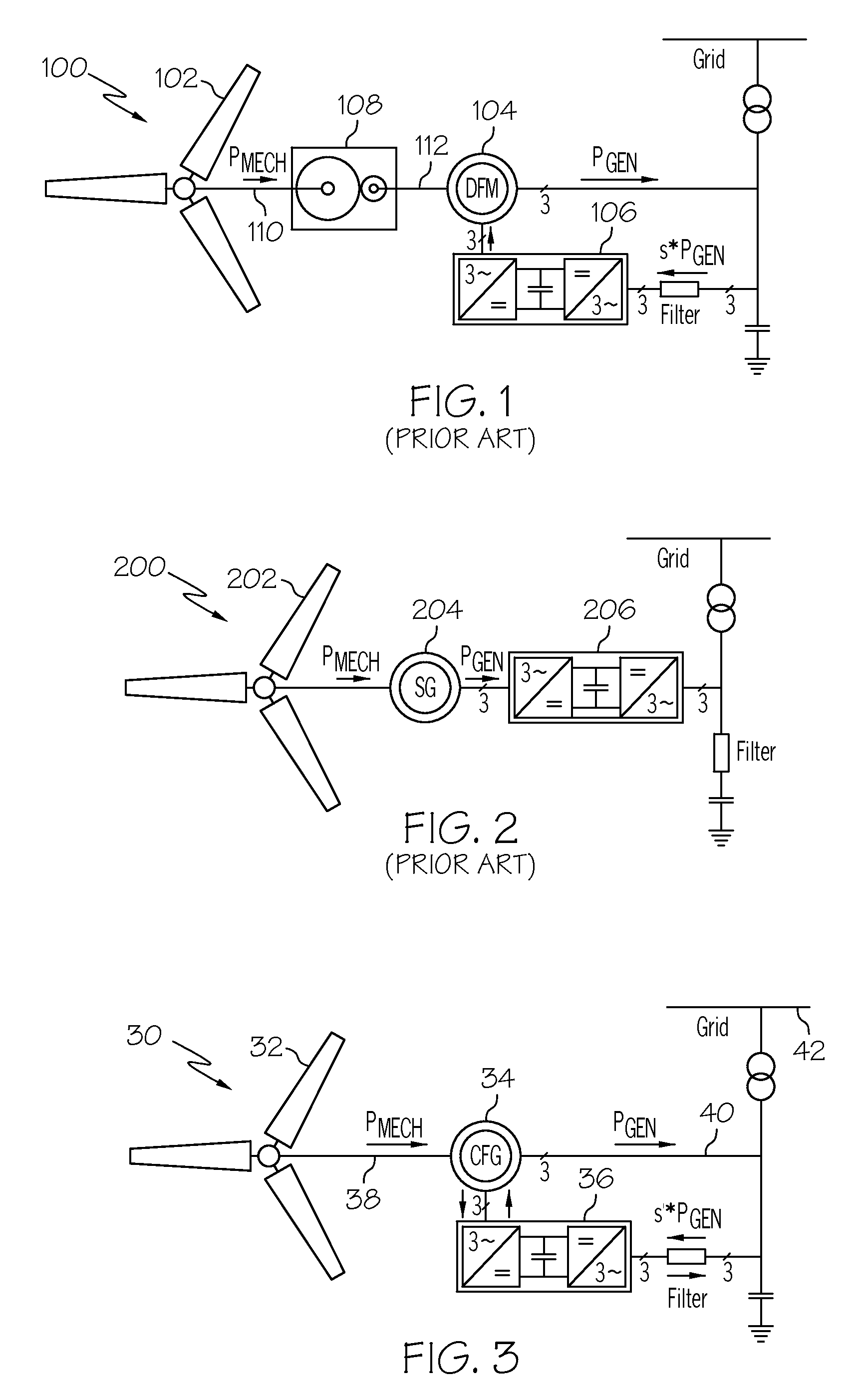
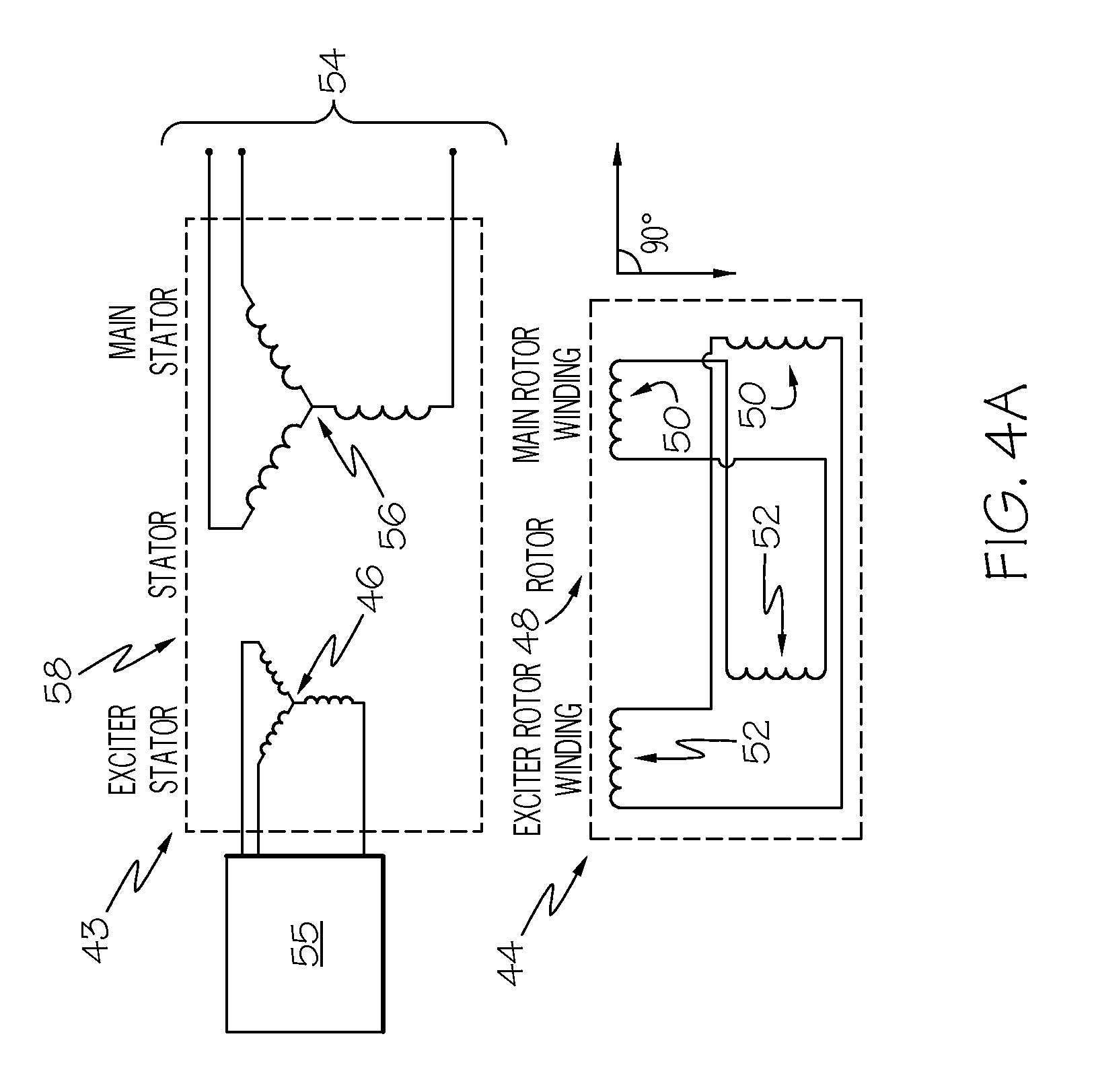
The present invention is related to a wind powered electricity generation apparatus that includes a wind turbine and a generator. The generator has at least two stages that are electrically connected to control the output frequency of the generator. The generator shaft has a variable speed, and the frequency at the output of the generator is controlled electrically using only a fraction of the total output power. This invention allows for the efficient generation of controlled frequency power from wind turbines without the need for a gearbox. The technical effects of this invention include improved efficiency and control over the output frequency of wind powered electricity generation.

Problems solved by technology

Because of the high torque and very low shaft speed (15 to 25 rpm) they are very large, heavy and expensive.
The low speed operation of direct-drive wind power systems dictates a large number of rotor poles in the generator.
This high number of rotor poles significantly increases the size, weight and cost of the generator.
Conventional direct-drive generators may also lack the ability to control the output frequency at 60 Hz.
The large electronic controller adds significant cost and weight to the wind turbine system.

Method used


Image

  • Multi-stage controlled frequency generator for direct-drive wind power
  • Multi-stage controlled frequency generator for direct-drive wind power
  • Multi-stage controlled frequency generator for direct-drive wind power

Examples


Embodiment Construction

[0034]The following detailed description is of the best currently contemplated modes of carrying out exemplary embodiments of the invention. The description is not to be taken in a limiting sense, but is made merely for the purpose of illustrating the general principles of the invention, since the scope of the invention is best defined by the appended claims.

[0035]Various inventive features are described below that can each be used independently of one another or in combination with other features.

[0036]Broadly, the present invention provides a direct-drive controlled frequency generator. By combining the advantageous performance and reliability of the direct-drive systems with a lower weight and cost similar to geared systems, the present invention may improve the implementation of generator systems for wind turbines. The shaft driving the generator in the direct-drive controlled frequency generator may be moved at a variable speed. The output frequency of the generator may be cont...


PUM


Abstract

A multi-sage controlled frequency generator is described that has a low size, weight and cost. The new generator requires an electronic controller that requires only 25% of the total generated power (100%) when the generator shaft speed varies by + / −25% around its synchronous speed. The shaft driving the generator in the direct-drive controlled frequency generator may be moved at a variable speed. The output frequency of the generator may be controlled by electrically controlling the frequency of the first stator stage and by selecting the control frequency, the number of poles, and the number of stages, such that the output of the last stage will be maintained constant at the desired grid frequency.

Description

CROSS-REFERENCE TO RELATED APPLICATIONS[0001]This application claims benefit under 35 USC 119(e) to provisional application No. 61 / 241,729, filed Sep. 11, 2009, herein incorporated by reference.BACKGROUND OF THE INVENTION[0002]The present invention generally relates a controlled frequency generator and, more specifically, to a multi-stage controlled frequency generator for direct-drive wind power.[0003]Wind power is a fast growing renewable energy source. Various wind turbine concepts have been developed with the goal of maximizing the energy harnessed, while minimizing the installation and operation costs and providing utility grid equivalent electrical power quality. Such turbine concepts can be classified into geared and direct-drive systems.[0004]FIG. 1 shows a functional block diagram of a conventional geared system 100. The major components of the geared system 100 include a wind turbine 102, a generator 104, a power converter 106, and a gearbox 108. Typically the generator 10...

Claims


Application Information

Patent Timeline
Patent Type & Authority Patents(United States)
IPC IPC(8): F03D9/00H02P9/04
CPCF03D9/002H02J3/386Y02E10/725Y02E10/763F03D9/25F03D15/10F03D9/255H02J2300/28H02J3/381Y02E10/76Y02E10/72
Inventor ANGHEL, CRISTIANXU, MINGMIRMOBIN, PARSA
Owner HONEYWELL INT INC
Learn More