Cancellation of oscillator remodulation

a technology of polar transmitter and remodulator, which is applied in the field of cancellation of polar transmitter remodulation, can solve the problems of disturbing the operation of the oscillator and remodulation can nevertheless happen in the polar transmitter, and achieve the effect of reducing or eliminating the remodulation of the signal generator and reducing the output signal of the transmitter

Active Publication Date: 2012-06-12
NXP BV
View PDF14 Cites 0 Cited by
  • Summary
  • Abstract
  • Description
  • Claims
  • Application Information

AI Technical Summary

Benefits of technology

[0009]By shifting the phase of the signal in the forward path of the transmitter by an appropriate amount, remodulation by the transmitter output signal can be reduced or eliminated.

Problems solved by technology

This parasitic signal can disturb the operation of the oscillator, especially if the parasitic signal has spectral content close to the oscillation frequency, where the oscillator is particularly sensitive.
However remodulation can nevertheless happen in a polar transmitter due to amplitude variations of the output signal, as occurs with non-constant envelope modulation.

Method used


Image

  • Cancellation of oscillator remodulation
  • Cancellation of oscillator remodulation

Examples


Embodiment Construction

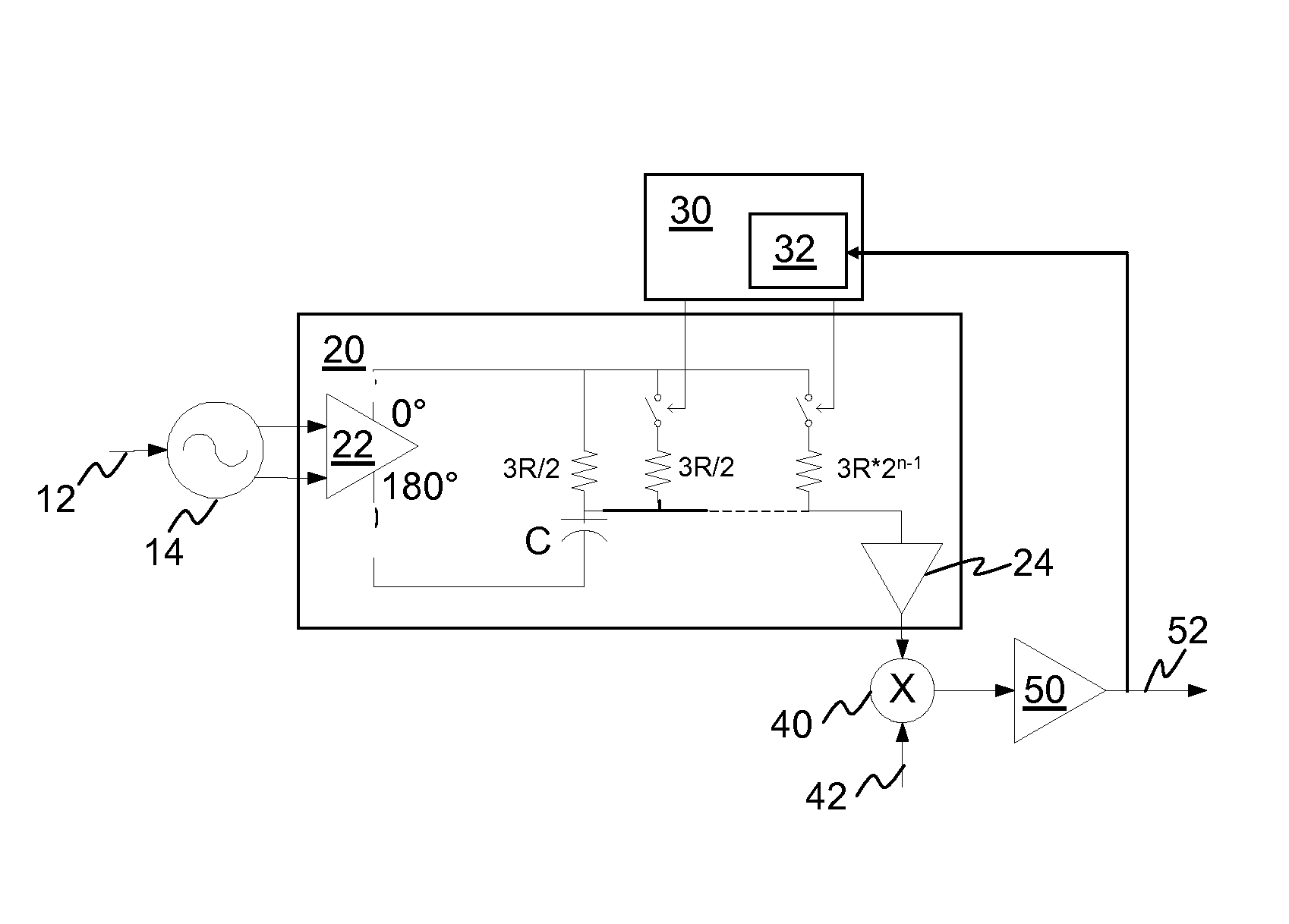
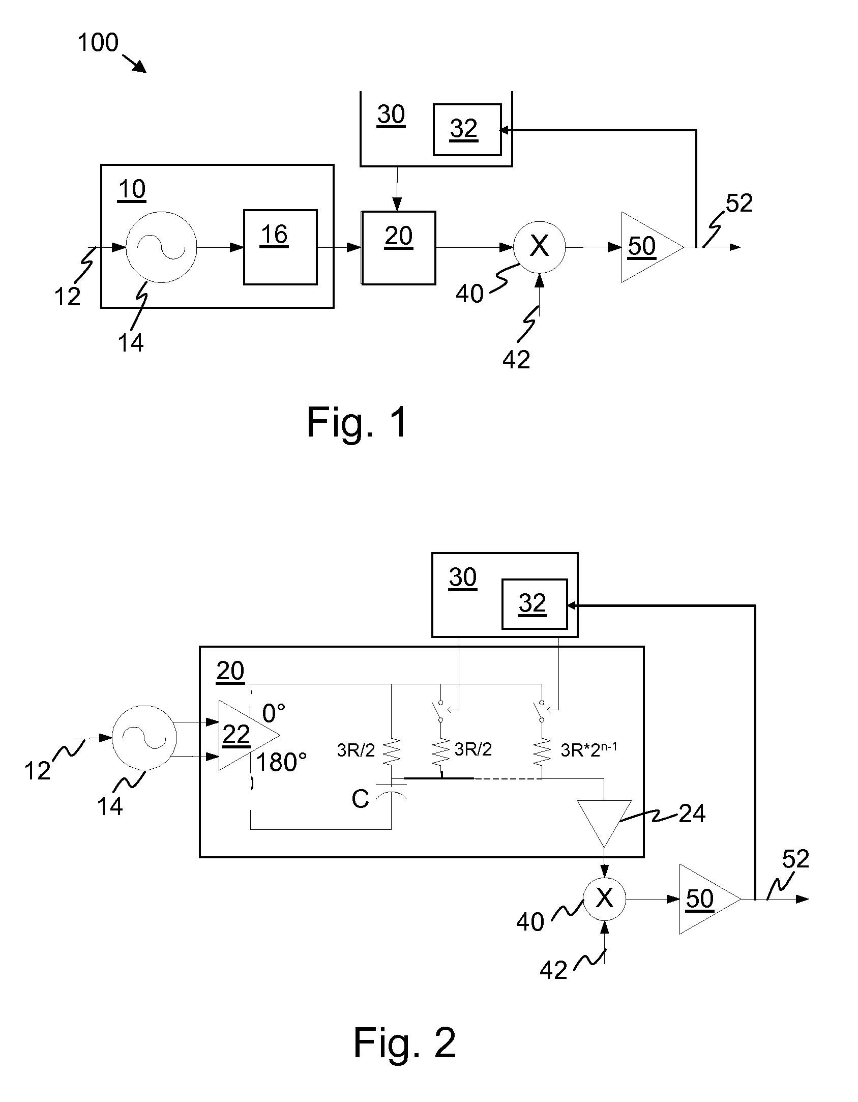
[0017]Referring to FIG. 1, there is illustrated a transmitter 100 comprising a signal generator 10 which includes an oscillator 14 for generating an oscillator signal and a divider 16 coupled to an output of the oscillator 14 for dividing the frequency of the oscillator signal. The oscillator 14 is a voltage controlled oscillator, and it has an input 12 for a first modulation signal for modulating the frequency of the oscillator signal. An output of the signal generator 10, coupled to an output of the divider 16, is coupled to an input of a phase shifting circuit 20 for phase shifting the signal delivered by the signal generator 10.

[0018]A controller 30 is coupled to an input of the phase shifting circuit 20 for controlling the extent of the phase shift. An output of the phase shifting circuit 20 is coupled to a first input of a mixer 40 for amplitude modulating the signal delivered by the phase shifting circuit 20 with a second modulation signal provided at a second input 42 of the...


PUM


Abstract

A wireless transmitter (100) comprises a signal generator (10) for generating a signal, an amplifier (50) for amplifying the signal, and a phase shifting circuit (20) coupled between the signal generator (10) and the amplifier (50) and arranged to shift the phase of the signal to cancel remodulation of the signal generator (10) by the amplified signal.

Description

FIELD OF THE INVENTION[0001]The invention relates to a wireless transmitter and to a method of operating such a transmitter. The invention has application in particularly, but not exclusively, polar transmitters.BACKGROUND TO THE INVENTION[0002]In a radio frequency (RF) transmitter comprising an oscillator and a power amplifier, oscillator remodulation can occur because of RF coupling between the power amplifier and the oscillator. This coupling is particularly likely to occur in transmitters where the power amplifier and the oscillator are manufactured in the same integrated circuit (IC) or in the same device package. As a result of the coupling, a fraction of the output power is injected back into the oscillator circuit as an unwanted parasitic signal. This parasitic signal can disturb the operation of the oscillator, especially if the parasitic signal has spectral content close to the oscillation frequency, where the oscillator is particularly sensitive. In response to such a clo...

Claims


Application Information

Patent Timeline
Patent Type & Authority Patents(United States)
IPC IPC(8): H04B1/04
CPCH03F1/3247H03F3/24H04B1/0475H03F2201/3231
Inventor PHILIPPE, PASCAL
Owner NXP BV
Why Eureka
Try Eureka