
Vehicle headlamp

a headlamp and headlamp technology, applied in the field of headlamps, to achieve the effect of reducing the number of components, saving power, and reducing weigh

Inactive Publication Date: 2012-06-19
ICHIKOH IND LTD
View PDF19 Cites 14 Cited by
  • Summary
  • Abstract
  • Description
  • Claims
  • Application Information

AI Technical Summary

Benefits of technology

[0028]the first reflecting surface is a reflecting surface made of a free curved face for light-distributing and controlling a reflection image of the light emitting chip, so that: the reflection image of the light emitting chip does not run out of the oblique cutoff line and the horizontal cutoff line; and a part of the reflection image of the light emitting chip is substantially in contact with the oblique cutoff line and the horizontal cutoff line;
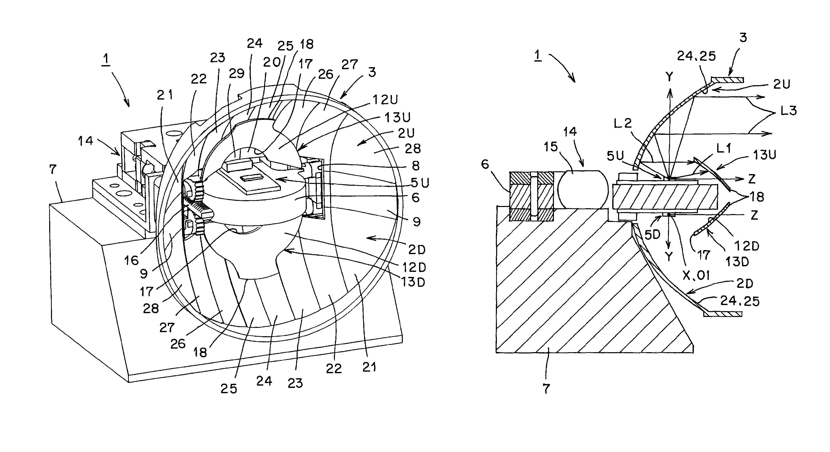
[0128]Furthermore, the vehicle headlamp according to the fourth aspect of the present invention is characterized in that the reflecting surface of the fixed reflector, the reflecting surface of the movable reflector, and the semiconductor-type light source are disposed so that an upside unit, a light emitting face of the light emitting chip being oriented upward in a vertical-axis direction, and a downside unit, a light emitting face of the light emitting chip being oriented downward in a vertical-axis direction, are established in a point-symmetrical state. As a result, even if at least one of the reflectors is downsized, luminous intensity of a respective one of a light distribution pattern for low beam and a light distribution pattern for high beam is sufficiently obtained, so that the vehicle headlamp according to the fourth aspect of the present invention becomes capable of further reliably performing both light-distributing and controlling of a light distribution pattern for low beam and a light distribution pattern for high beam, which are optimal for vehicle use, and downsizing of a lamp unit.

Problems solved by technology

Thus, the conventional vehicle headlamp requires a large number of components and the second light source unit for a light distribution pattern for high beam, and entails problems concerning downsizing, weight reduction, power saving, and cost reduction, accordingly.

Method used


Image

  • Vehicle headlamp
  • Vehicle headlamp
  • Vehicle headlamp

Examples


embodiment (

Embodiment(s)

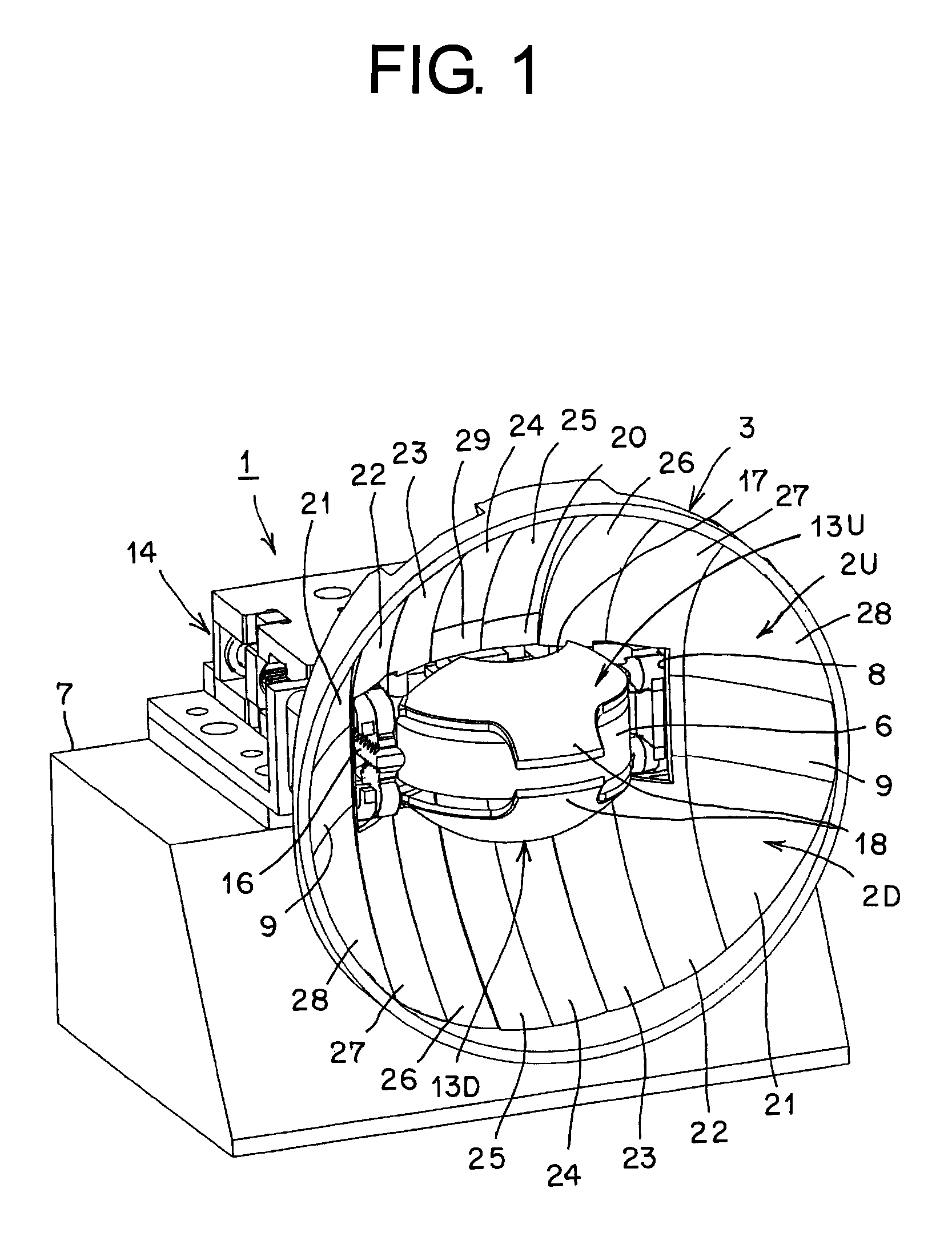
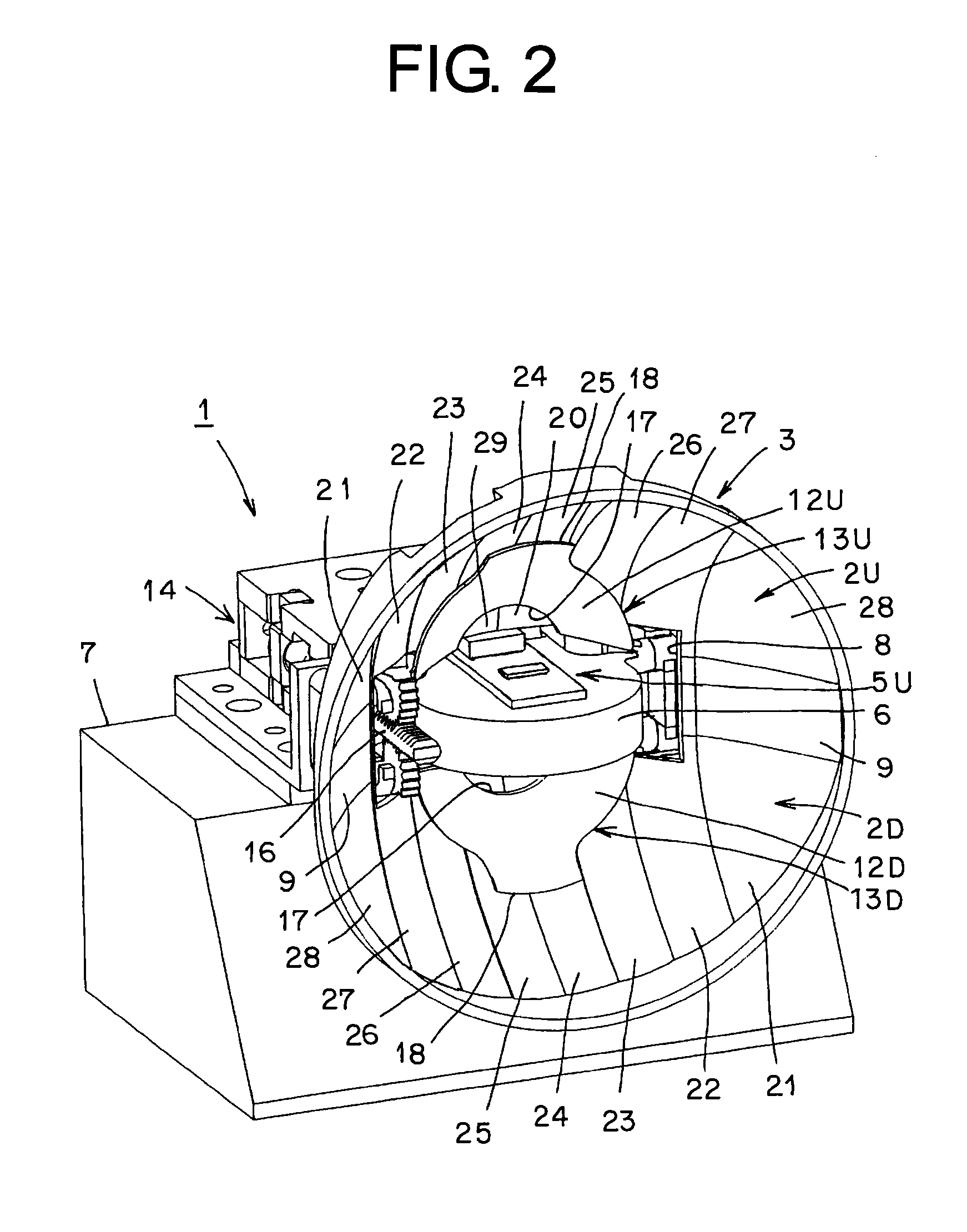
[0151]Hereinafter, a configuration of a vehicle headlamp in the embodiment will be described. In the figures, reference numeral 1 denotes a vehicle headlamp (automobile headlamp) in the embodiment. The vehicle headlamp 1 illuminates light toward a forward direction of a vehicle by changing: a light distribution pattern for passing (light distribution pattern for low beam), shown in FIG. 20, i.e., a light distribution pattern LP for low beam, having an oblique cutoff line CL1 on a cruising lane side (left side) and a horizontal cutoff line CL2 on an opposite lane side (right side) with an elbow point E being a boundary; and a light distribution pattern for cruising (light distribution pattern for high beam), shown in FIG. 21, i.e., a first light distribution pattern HP1 for high beam, a second light distribution pattern HP2 for high beam, a third light distribution pattern HP3 for high beam, and a light distribution pattern LP1 for dimming low beam. An angle formed betwe...


PUM


Abstract

A vehicle headlamp is provided with: a fixed reflector having reflecting surfaces, a respective one of which is made of a parabola-based free curved face; movable reflectors having reflecting surfaces, a respective one of which is made of a parabola-based free curved face; and semiconductor-type light sources, a respective one of which has a light emitting chip shaped like a planar rectangle. When the movable reflectors are positioned in a first location, a light distribution pattern for low beam is obtained on the reflecting surfaces of the fixed reflector. When the movable reflectors are positioned in a second location, light distribution patterns for high beams are obtained on the reflecting surfaces of the fixed reflector and the movable reflector. As a result, the vehicle headlamp enables downsizing, weight reduction, power saving, and cost reduction.

Description

CROSS-REFERENCE TO RELATED APPLICATIONS[0001]This application claims priority of Japanese Patent Application No. 2008-280070 filed on Oct. 30, 2008. The contents of this application are incorporated herein by reference in their entirety.BACKGROUND OF THE INVENTION[0002]1. Field of the Invention[0003]The present invention relates to a vehicle headlamp for illuminating light to a forward direction of a vehicle by changing a light distribution pattern for low beam (light distribution pattern for passing) and a light distribution pattern for high beam (light distribution pattern for cruising).[0004]2. Description of the Related Art[0005]A vehicle headlamp of this type is conventionally known (Patent Document 1: Japanese Laid-open Patent Application No 2007-109493, for example). Hereinafter, a conventional vehicle headlamp will be described. The conventional vehicle headlamp is made up of: a first light source unit forming a light distribution pattern for low beam; and a second light sou...

Claims


Application Information

Patent Timeline
Patent Type & Authority Patents(United States)
IPC IPC(8): F21V7/06B60Q1/04F21W107/10
CPCF21S48/1159F21S48/1163F21S48/1757F21Y2101/02F21Y2115/10F21S41/155F21S41/675F21S41/148
Inventor OOKUBO, YASUHIROABE, TOSHIYA
Owner ICHIKOH IND LTD
Learn More