Atomizer and emission analyzer

An atomizer and plasma technology, used in thermal excitation analysis, material excitation analysis, plasma, etc., can solve the problems of voltage time delay, poor atomization efficiency, low luminous intensity, etc., to improve accuracy, suppress dispersion, The effect of increased luminous intensity

Active Publication Date: 2013-04-03
NAT UNIV CORP TOKAI NAT HIGHER EDUCATION & RES SYST
View PDF5 Cites 0 Cited by
  • Summary
  • Abstract
  • Description
  • Claims
  • Application Information

AI Technical Summary

Problems solved by technology

[0007] However, in the case of using an industrial AC power supply, since the voltage rises slowly, there is a time delay until the discharge start voltage is reached, and the efficiency of atomization is poor.
Therefore, the emission intensity is low for the type of target element, making measurement difficult
[0008] In addition, since the atomizer of Patent Document 1 has two power sources, it is not possible to make the device compact and portable.

Method used


Image

  • Atomizer and emission analyzer
  • Atomizer and emission analyzer
  • Atomizer and emission analyzer

Examples


Embodiment 1

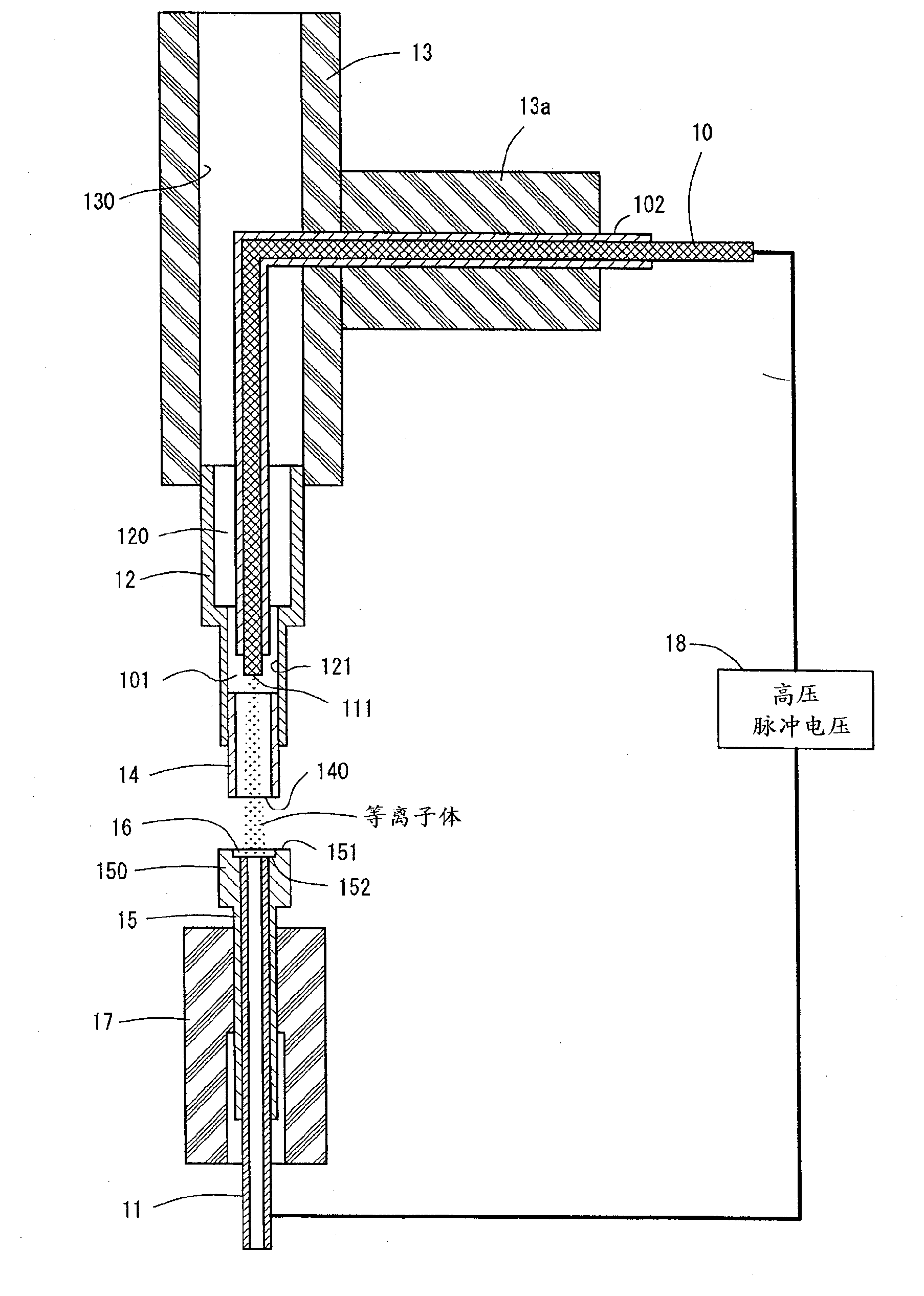
[0042] figure 1 It is a figure showing the structure of the atomizer of Example 1. The atomizer of Example 1 has a rod electrode 10 (the first electrode of the present invention) and a sample electrode 11 (the second electrode of the present invention). The rod-shaped electrode 10 has a rod-shaped structure made of Cu with a diameter of 1.2 mm, and the sample electrode 11 has a tubular structure made of stainless steel with an outer diameter of 2 mm and an inner diameter of 1 mm. The outer peripheral surface of the rod electrode 10 is covered with an insulator 102 .

[0043] For the rod electrode 10, stainless steel, molybdenum, tungsten, etc. can be used other than Cu. In addition, Cu, molybdenum, tungsten, etc. can be used for the sample electrode 11 other than stainless steel. However, in consideration of the problem that the sample electrode 11 itself will be atomized to affect the analysis, it is necessary to use a material that does not contain the target element for ...

Embodiment 2

[0061] Next, Example 2 will be described. Figure 8 It is a figure which shows the structure of the atomizer of Example 2. The atomizer of Example 2 has a rod electrode 10 (the first electrode of the present invention) and a sample electrode 11 (the second electrode of the present invention). The rod-shaped electrode 10 is a rod made of Cu with a diameter of 1.2 mm, and the sample electrode 11 is a tube made of stainless steel with an outer diameter of 2 mm and an inner diameter of 1 mm.

[0062] For the rod electrode 10 , other than Cu, stainless steel, molybdenum, tungsten, or the like can be used. In addition, Cu, molybdenum, tungsten, etc. can be used for the sample electrode 11 other than stainless steel. However, in consideration of the problem that the sample electrode 11 itself will be atomized to affect the analysis, it is necessary to use a material that does not contain the target element for the sample electrode 11, or perform coating, electroplating, etc. with a...

experiment example 1

[0073] Figure 11 It is a graph showing the results of measuring the light-receiving angle dependence of the emission intensity of the atmospheric-pressure plasma obtained by the atomizer of Example 2. The horizontal axis represents the light receiving angle, and the light receiving angle is the angle formed by the straight line connecting the sample and the light receiving device and the plane perpendicular to the opposing direction (axial direction) of the rod electrode 10 and the sample electrode 11 . The light receiving device is an optical fiber provided with a lens at the end, and the optical fiber is connected with the light splitting device. The sample is water containing 1ppm of Cu, and the luminous intensity of Cu at the resonance line spectral wavelength (324.75nm) is measured by a light receiving device. In addition, the distance between the rod electrode 10 and the sample electrode 11 was 4 mm, and the distance from the sample to the light receiving device was 4 mm...


PUM

PropertyMeasurementUnit
diameteraaaaaaaaaa
diameteraaaaaaaaaa

Abstract

Disclosed is an atomizer which can provide improved atomization efficiency. The atomizer has a stick electrode (10) and a sample electrode (11) that is spaced apart by a certain distance from the tip portion of the stick electrode (10). The tip portion of the stick electrode (10) is axially aligned with and accommodated in a ceramic pipe (14). A gap is provided between the inner wall of the ceramic pipe (14) and the stick electrode (10) to allow a discharged gas to flow axially through the gap towards the tip portion of the stick electrode (10). The sample electrode (11) is covered with a ceramic pipe (15), the tip of which is increased in outer diameter and has a bowl-shaped recessed portion (16). At the bottom surface of the recessed portion (16), the sample electrode (11) is exposed. This recessed portion holds a sample. The stick electrode (10) and the sample electrode (11) are connected to a high-voltage pulse power supply (18). As shown in Fig. 2, the high-voltage pulse power supply (18) outputs rectangular pulsed voltages which are alternately inverted between positive and negative.

Description

technical field [0001] The present invention relates to an atomizer for atomizing a target element in a sample by using atmospheric pressure plasma, and is characterized in the aspect of a power supply for generating atmospheric pressure plasma. In addition, the present invention relates to a light emission analyzer using the atomizer. Background technique [0002] In atomic absorption analysis and atomic emission analysis, a device (atomizer) is required to atomize the sample, but in the past, graphite furnace was used for atomic absorption analysis, and ICP device was used for atomization in atomic emission analysis. devices are widely used. In addition, as in Patent Document 1, an atomizer using atmospheric pressure plasma is also known. [0003] Patent Document 1 describes the following emission analysis method. First, the atomizer is used to irradiate the sample containing the target element with atmospheric pressure plasma to atomize the sample, and the metal elemen...

Claims


Application Information

Patent Timeline
Patent Type & Authority Applications(China)
IPC IPC(8): G01N21/73H05H1/24
CPCH05H1/48G01N21/74H05H2001/483H05H1/471
Inventor 堀胜加纳浩之
Owner NAT UNIV CORP TOKAI NAT HIGHER EDUCATION & RES SYST
Why Eureka
Try Eureka